USER MANUAL-S600E
86
S600E
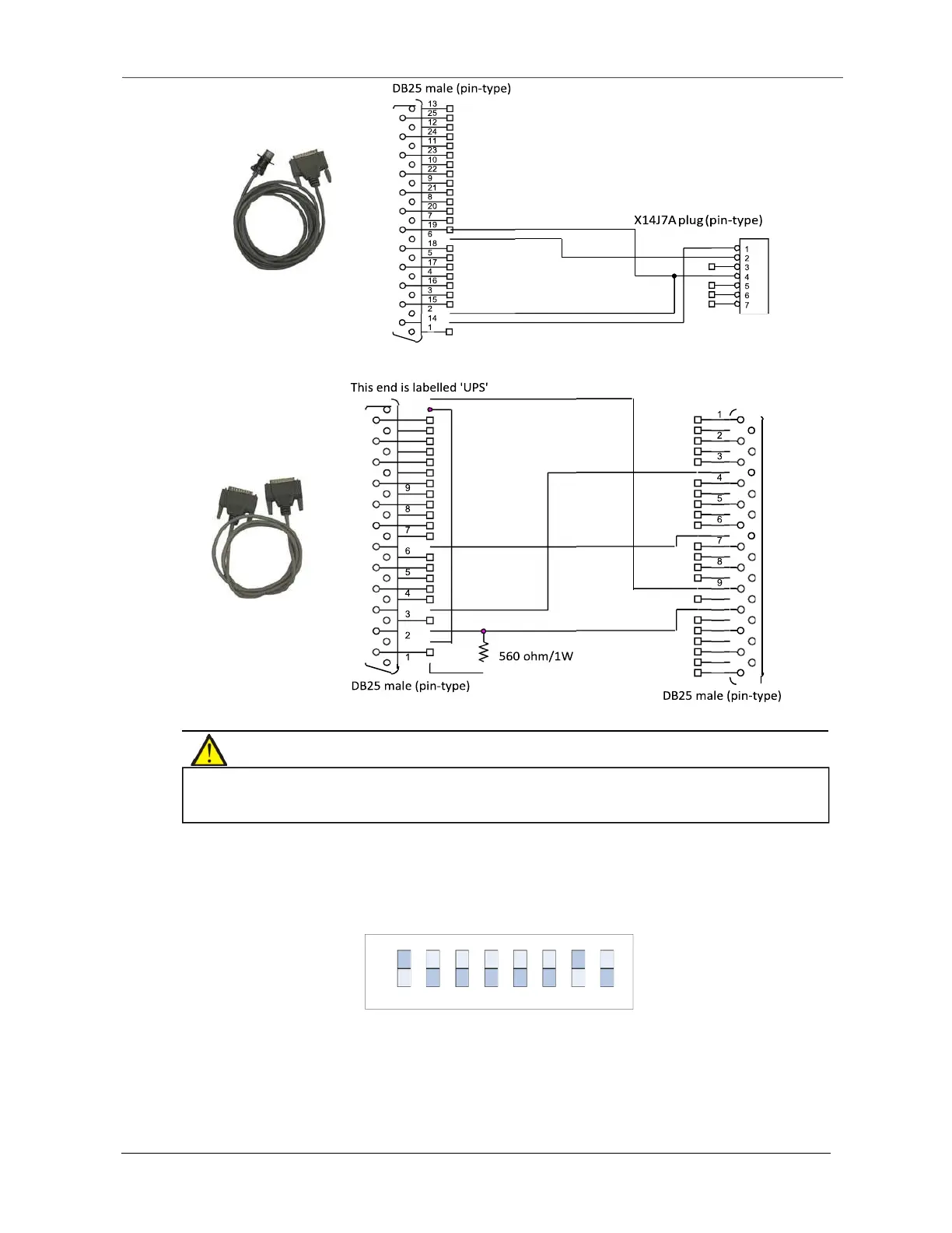
This end is labelled "UPS"
DB25 male (pin-type)
DB25 male (pin-type)
Figure 8-11 Appearance and wiring diagram of cable 2 (UFDRY21SL2)
Installation
Figure 8-12 Appearance and wiring diagram of cable 3 (UFDRY21SL3)
1.
Set the DIP switch on the relay card.
Skip this step if you do not need to control the UPS switch-on and switch-off functions via the relay card.
The location of the DIP switch is shown in Figure 8-13. It is an 8-bit DIP switch. Its factory default setting is shown in Figure
8-6.
Figure 8-13 DIP switch factory default setting
Bits
1
through 7 are designed for use in the factory, the user is not permitted to change their default settings. Bit 8 is
used to configure the UPS switch-on and switch-off signal input function on the relay card, see Table 8-4 for
instructions on how to set it.
the relay card, do not touch its electronic components or circuits, also make sure that they do not come into contact with
live parts. Please hold the relay card by its edges when handling or installing it.
13
25
12
24
11
23
10
22
21
20
19
18
17
16
15
14
14
15
16
17
18
19
20
21
22
10
23
11
24
12
25
13
ON
OFF
1 2 3 4 5 6 7 8