USER MANUAL-S600E
85
S600E
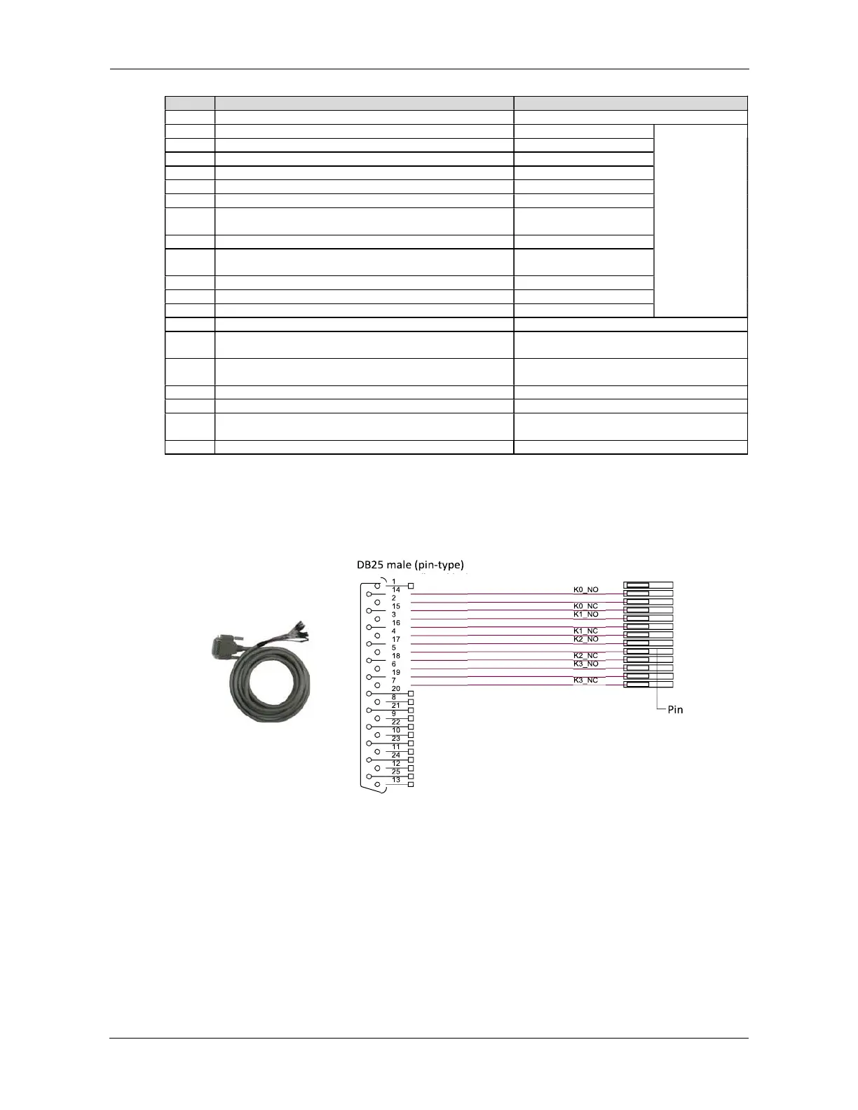
DB25 male (pin-type)
Table 8-3 DB25 connector pin description
15Vdc (reserved for factory use)
K0_NO, Channel 0 dry contact normally open output contact
Electrical
parameter:
30Vdc/1.8A,
resistive load
K0_COM, Channel 0 dry contact common output contact
K0_NC, Channel 0 dry contact normally closed output contact
K1_COM, Channel 1 dry contact common output contact
dry contact normally closed output contact
Pin 17
K2_NO, Channel 2 dry contact normally open output contact
K2_COM, Channel 2 dry contact common output contact
Pin 18
K2_NC, Channel 2 dry contact normally closed output contact
Open: UPS on Bypass or in
K3_NO, Channel 3 dry contact normally open output co
K3_COM, Channel 3 dry contact common output contact
K3_NC, Channel 3 dry contact normally closed output contact
Pin 12 DRY_IN1, Channel 1 dry contact signal input
Pin 25
DRY_IN0, Channel 0 dry contact signal input
ation to PC, receive terminal
Reserved, for factory commissioning
TXD_PC, for communication to PC, send terminal
Reserved, for factory commissioning
Pin 13 GND, common GND
dry contact signal input common
Cable options
VERTIV provides three cable options for connections to the DB25 connector of the relay card, depending on the
user’s requirements
Figure 8-10 - Figure 8-12 show the appearance and wiring principle of each cable.
Figure 8-10 Appearance and wiring diagram of cable 1 (UFDRY21SL1)
K0_COM
K1_COM
K2_COM
K3_COM