2 INSTALLATION AND CONFIGURATION
The following sections are provided to install and configure your RPC2 communications module.
2.1 Getting Started
The RPC2 communications module is factory installed on Vertiv® rack PDUs. If the module is being field-installed, see the
following section, Required cables, to ensure you have all the necessary items for proper installation.
Installation and utilization of the RPC2 module is identical for vertical and horizontal rack PDUs. The following figure shows
an RPC2 module installed in a vertical MPH2™ rack PDU.
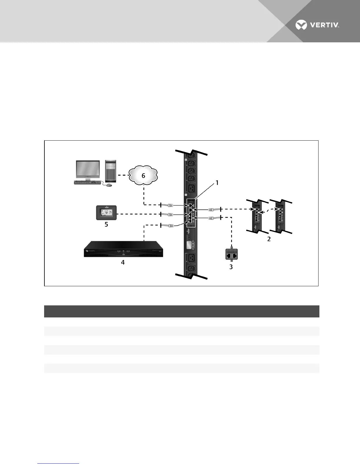
Figure 2.1 RPC2 Communications Module Configuration
ITEM DESCRIPTION
1 RPC2 Communications Module
2 Additional MPH2 Rack PDUs configured in an array
3 Sensor
4 Console server of switch
5 Basic Display Module (BDM)
6 Network
Table 2.1 RPC2 Communicatons Module Configuration Descriptions
2.1.1 Required cables
The following cables are not included but are necessary for RPC2 communications module functionality:
• RJ45 cable for connection to the serial port
• RJ45/DB9Fadaptor or equivalent is required to connect to Avocent™ appliances.
• RJ45 CAT5E or CAT6 Ethernet cable for the network port connection
• RJ45 CAT5 or better Ethernet cable for the link port connection
Vertiv | RPC2™ Communications Module Installer/User Guide | 3