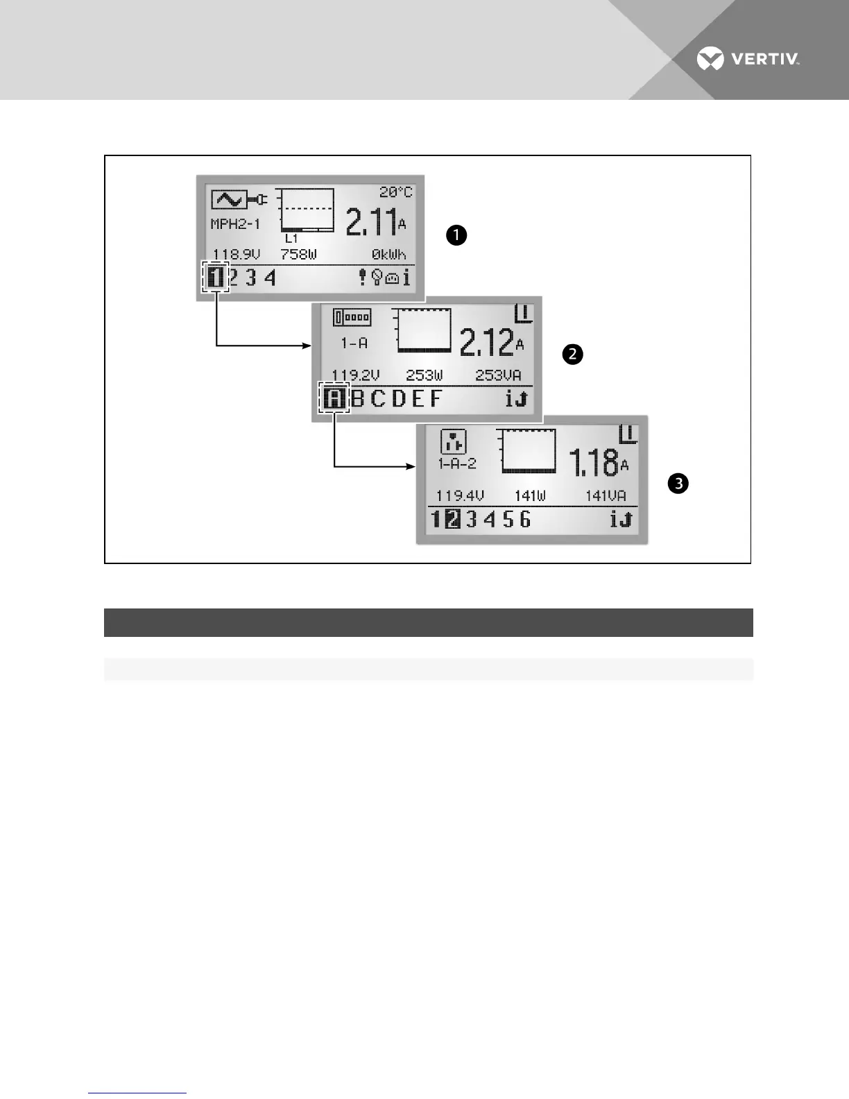
Figure 4.4 BDMHierarchy
ITEM DESCRIPTION
1 PDULevel
2 Branch Level
3 Receptacle Level
Table 4.3 BDM Hierarchy Descriptions
The icon in the upper-left corner of the screen identifies the component type, PDU, branch or receptacle. The highlighted ID
number in the lower-left corner indicates which component is currently displayed, for example PDU1, Branch A, Receptacle
5. A selected component blinks while data about it is displayed.
The component data includes a graph, amperage and status (V, W, VA for branch/receptacle). Navigation buttons appear in
the lower-right corner of each screen. When any events are detected, the display changes to the PDU view and an Active
Events icon appears in the lower-right corner.
4.4.1 PDUlevel
Select a PDU number in the lower-left corner to highlight it. The screen displays information for the selected PDU. The
following figure is an example of data for PDU #1, one of two PDUs that are communicating with the BDM unit. The PDU view
displays information collected at the PDU input point for each of the three input phases: L1, L2 and L3. Up to three phases
can be used.
Vertiv | RPC2™ Communications Module Installer/User Guide | 38