• Receptacle Level - provides status information and power monitoring of each receptacle (available on certain
models of the Vertiv® MPH2™ and MPX™ rack PDUs).
2.3.2 Rack PDU component ID
An alphanumeric ID consisting of up to three parts helps you identify components when displayed on the web interface or
the RPC BDM device. The component ID uses the format PDU-Branch-Receptacle. For example, the component ID 1-A-3
identifies PDU1, Branch A and Receptacle 3.
NOTE: MPH2™ rack PDUs use alphabetical characters to designate a branch whereas MPX™and MPH™ rack PDUs
use numerical characters. So Branch Aon an MPH2™ PDUis effectively Branch 1 on an MPX™or MPH™ PDU.
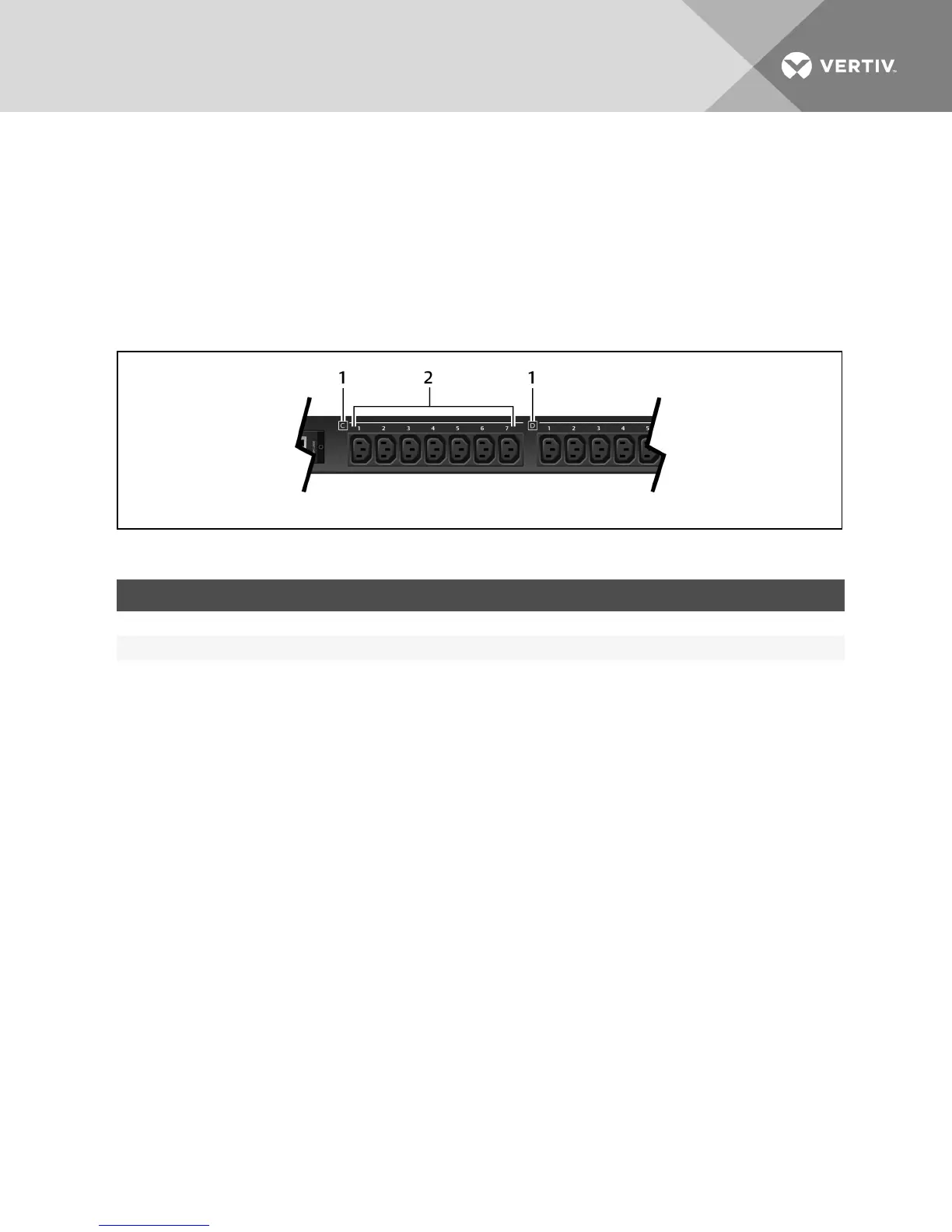
Figure 2.3 MPH2™ Branch and Receptacle Labeling Example
ITEM DESCRIPTION
1 Letters displaying the branch level.
2 Numbers displaying the receptacle level.
Table 2.3 Rack Component ID Descriptions
2.4 Creating a Rack PDU Array
Up to four MPH2 or Liebert MPX rack PDUs may be integrated into a rack PDU array, which permits central control and
monitoring of each rack PDU through a single web interface. Each rack PDU must have an RPC2 communications module
installed.
NOTE: Creating a Rack PDU array does not require rebooting or powering off either the MPH2 rack PDUs or the
connected load. The level of monitoring and control depends on the model of rack PDU.
To set up a rack PDU array:
1. Log in with the required privileges.
2. Connect an Ethernet cable from a computer or network switch to the Network port of the master RPC2
communications module.
3. Connect an Ethernet cable to the Link port of the master RPC2 communications module.
4. Connect the other end of the Ethernet cable to the network port of a slave RPC2 communications module on a
second MPH2. This RPC2 module is a sibling unit, accessible through the master RPC2 module.
NOTE: The RPC2 module connected to the LAN is the master and is positioned first in the rack PDU array.
5. The second RPC2 communications module automatically detects the connections and is discovered as a
sibling unit.
NOTE: If the sibling order needs to be changed, disconnect the cabling for 30 seconds and then reconnect in the
desired sequence. You do not need to reboot or power cycle the module.
6. Connect additional RPC2 communications modules as shown in the following figure. The Ethernet cable
attaches from the link port of an RPC2 module that has been added to the array to the next module’s network
port. Each newly added module is discovered as the next sibling.
Vertiv | RPC2™ Communications Module Installer/User Guide | 5