Assembly - attachment
24
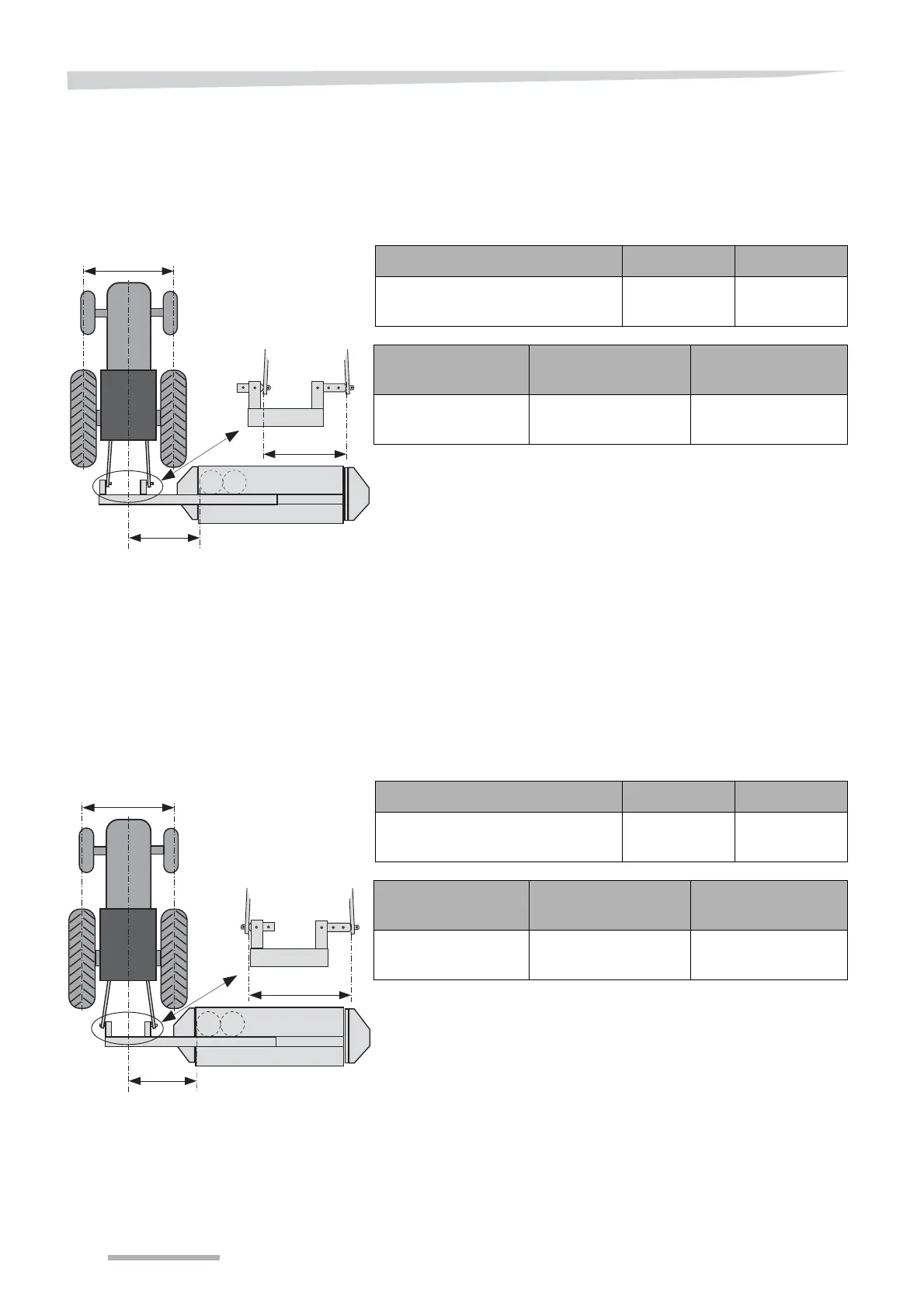
The following setting for the linkage pins must be used for attachment:
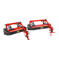
category 1
Model 117 only
*The linkage pins are mounted so that the lift arms are coupled to the
tractor on the right-hand side of the coupling frame as shown.
category 2
The linkage pins are mounted so that the lift arms are coupled to the
tractor as follows:
• Left-hand lift arm on the tractor: mounted to the left-hand side of
the coupling frame.
• Right-hand lift arm on the tractor: mounted to the right-hand side of
the coupling frame.
Category 1 linkage pins for model 122 -124 are extra equipment.
»Optional equipment« page 84
“A” (Minimum) “B” “C”
1500 mm
(59”)
684 mm
(27”)
926 mm
(36”)
Gauge “A” Left-hand linkage
pin
Right-hand
linkage pin
1500 mm
(59”)
Short linkage pin* Long linkage pin*
A
B
C
“A” (Minimum) “B” “C”
1500 mm
(59”)
825 mm
(32½”)
998 mm
(39”)
Gauge “A” Left-hand linkage
pin
Right-hand
linkage pin
1500 mm
(59”)
Short linkage pin Long linkage pin
A
B
C