Assembly - attachment
25
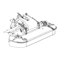
The linkage pins are mounted so that the lift arms are coupled to the
tractor as follows:
• Left-hand lift arm on the tractor: mounted to the left-hand side of
the coupling frame.
• Right-hand lift arm on the tractor: mounted to the right-hand side of
the coupling frame.
Category 1 linkage pins for model 122 -124 are extra equipment.
»Optional equipment« page 84
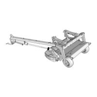
“A” (Minimum) “B” “C”
1600 mm
(63”)
825 mm
(32 ½”)
1048 mm
(41”)
Gauge “A” Left-hand linkage
pin
Right-hand
linkage pin
1600 mm
(63”)
Short linkage pin Long linkage pin
“A” (Minimum) “B” “C”
1700 mm
(67”)
825 mm
(32 ½”)
1098 mm
(43”)
Gauge “A” Left-hand linkage
pin
Right-hand
linkage pin
1700 mm
(67”)
Long linkage pin Short linkage pin
A
B
C
A
B
C