Chapter 4 Analog input/output modules Manual VIPA System 200V
4-2 HB97E - SM-AIO - Rev. 12/32
General
You must only use screened twisted-pair cable for analog signals. These
cables reduce the effect of electrical interference. The screen of the analog
signal cable should be grounded at both ends. In situations where the cable
ends are at different electrical potentials, it is possible that a current will
flow to equalize the potential difference. This current could interfere with the
analog signals. Under these circumstances it is advisable to ground the
screen of the signal cable at one end only.
Our analog modules provide a large number of configuration options
suitable for 2wire and 4wire transducers. Please remember that
transducers require an external power source. You have to connect an
external power supply in line with any 2wire transducer.
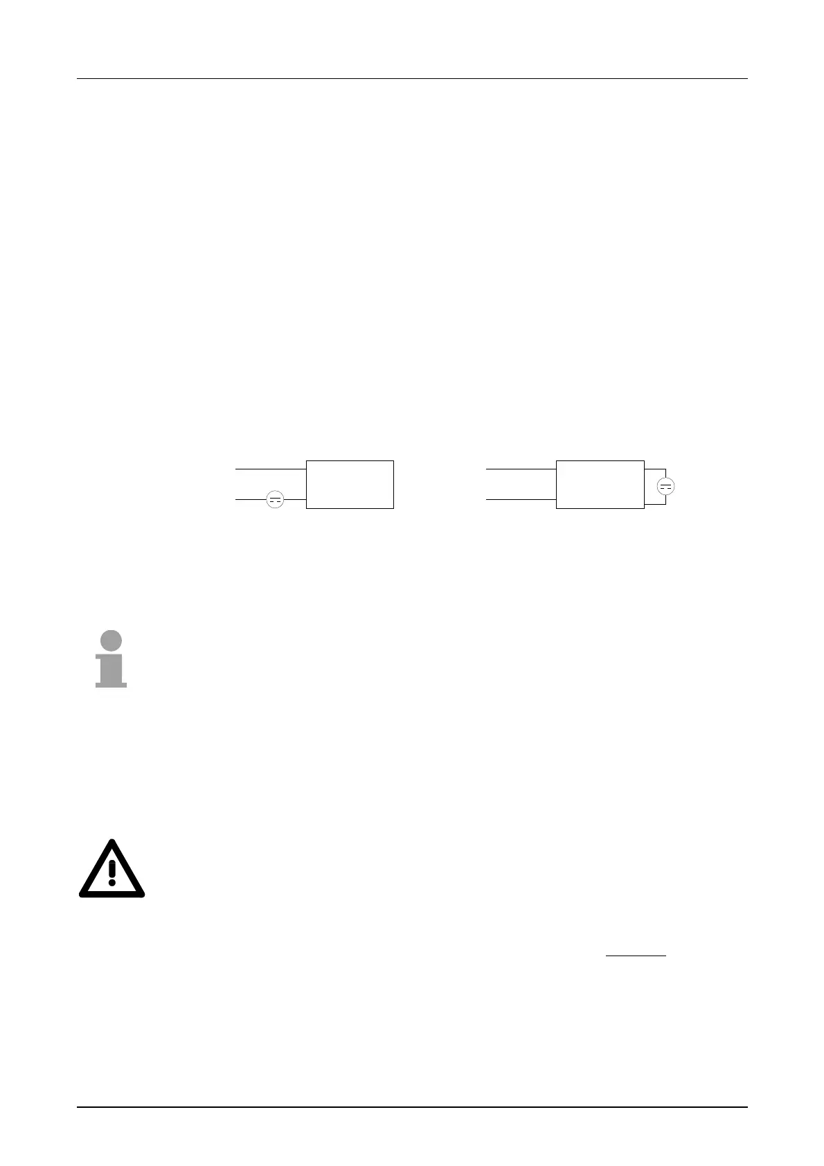
The following diagram explains the connection of 2- and 4wire transducers:
2wire interfacing 4wire interfacing
transducer transducer
Due to the fact that actuators also require a source of external power, they
may also be connected with 2 or 4wires. Where control signals are supplied
to 2wire actuators a power supply has to be connected in series with the
control cable. 4wire actuators need an external power source.
Note!
Please ensure that you connect actuators to the correct polarity!
Unused output terminals must not be connected!
By using the SFCs 55, 56 and 57 you may change the parameters of the
analog modules during runtime via the CPU 21x.
For diagnosis evaluation during runtime, you may use the SFCs 51 and 59.
They allow you to request detailed diagnosis information and to react to it.
Attention!
Temporarily not used inputs have to be connected with the concerning
ground at activated channel. When deactivating unused channels by
means of FFh, this is not required.
The following circumstances may cause damages at the analog module:
• The external supply of the input (current/voltage) must not be present
as long as the backplane bus of the CPU is still without current supply!
• Parameterization and connection of the input must be congruent!
• You must not apply a voltage >15V to the input!
Cabling for
analog signals
Connecting
sensors
Connecting loads
and actuators
Parameterization
and diagnosis
during runtime