Manual VIPA System 200V Chapter 4 Analog input/output modules
HB97E - SM-AIO - Rev. 12/32 4-3
234-1BD50 - AI 2/AO 2x12Bit - Multiin-/output
AI 2/AO 2x12Bit Multiin-/output VIPA 234-1BD50
This module has 2 analog inputs and 2 analog outputs that may be
configured individually. The module occupies a total of 4byte of input and
4byte of output data.
Galvanic isolation between the channels on the module and the backplane
bus is provided by means of DC/DC converters and optocouplers. The
module requires an external supply of DC 24V.
• 2 inputs and 2 outputs with common ground
• In-/Outputs with individually configurable functions
• Suitable for encoder res. actuators with in- res. output ranges of:
±10V, 1...5V, 0...10V, ±20mA, 0...20mA or 4...20mA
• Diagnostic LED
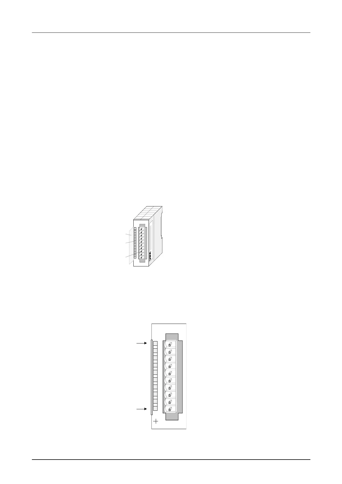
1
[1]
[2]
[3]
Label for the bit address
with description
LED status indicator
Edge connector
LED
L+
SF
Description
LED (yellow)
Supply voltage present
Sum error LED (red)
turned on as soon as an
channel error is
detected res. an entry in
the diagnostic bytes
happened
AI2/AO2 x12Bit
SM 234
L+
+0
M0
+1
M1
Q0
M0
Q1
M1
SF
VIPA 234-1BD50
X2
34
1
2
3
4
5
6
7
8
9
I0
Pin
1
2
3
4
5
6
7
8
9
10
Assignment
DC 24V supply voltage
pos. connection Ch.0
Ground Channel 0
pos. connection Ch.1
Ground Channel 1
pos. connection Ch.2
Ground Channel 2
pos. connection Ch.3
Ground Channel 3
Supply voltage Ground
Order data
Description
Properties
Construction
Status indicator
Pin assignment