Manual VIPA System 200V Chapter 5 238-2BC00 - Combination module
HB97E - SM-AIO - Rev. 12/32 5-7
Analog part - Project engineering
The combination module can only be used together with a CPU 21x or with
the DP-V1 Profibus coupler (253-xDP01)! The project engineering takes
place in the Siemens SIMATIC manager. For this the import of the
corresponding GSD file is required which can be found at the "service" area
on www.vipa.com.
After installation of the GSD file the combination module can be found at
the hardware catalog at:
Additional Field devices > I/O > VIPA_System_200V > ...
as 2 modules:
238-2BC00 (1/2) AI4/AO2*12Bit
238-2BC00 (2/2) Counter
Please take care that you always configure both module parts in the
sequence shown above
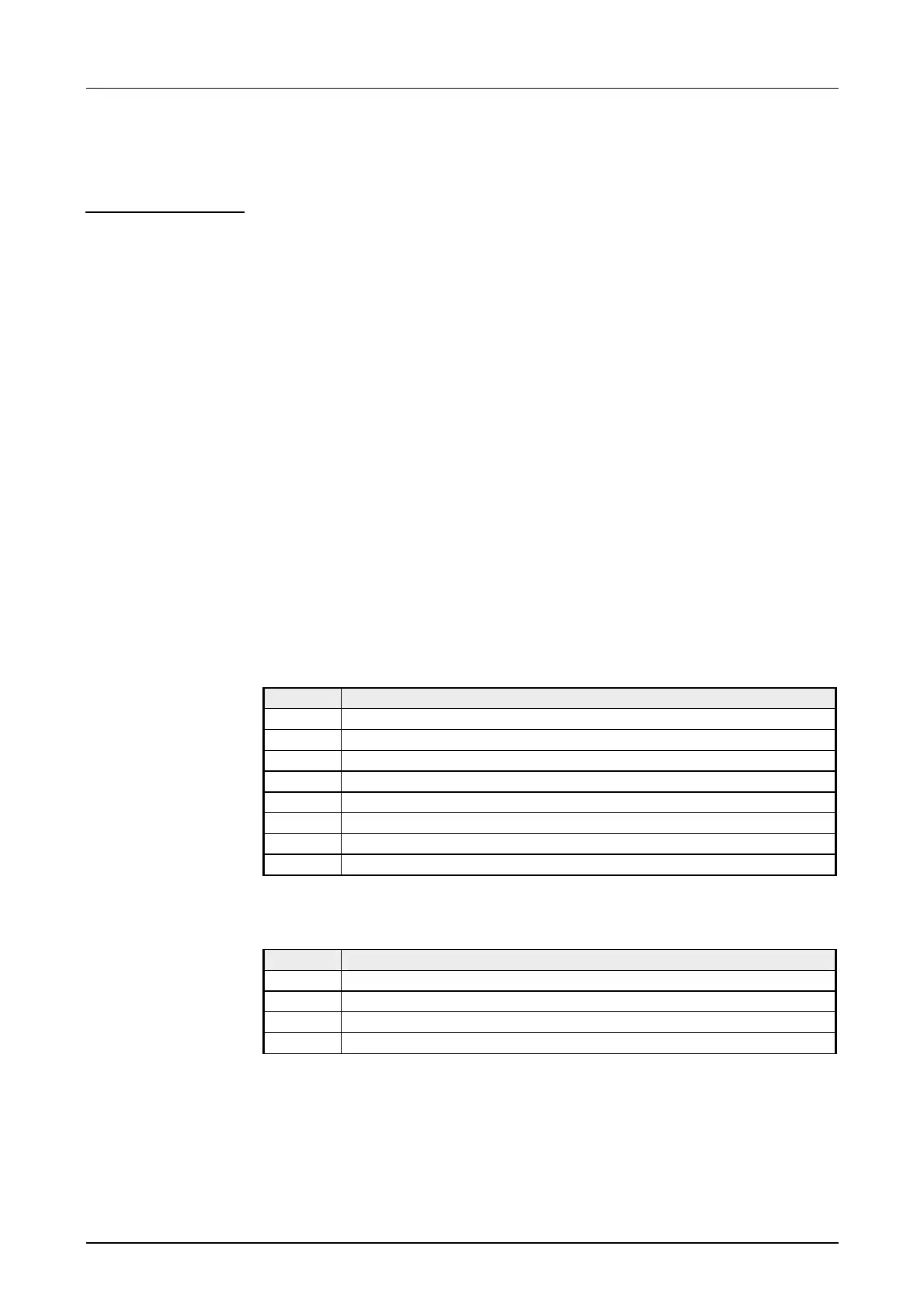
For data input 8bytes and for data output 4bytes are available with the
following assignment:
Data input range:
During the measuring, the measuring values are stored in the data input
area.
Byte Bit 7 ... Bit 0
0 High-Byte channel 0
1 Low-Byte channel 0
2 High-Byte channel 1
3 Low-Byte channel 1
4 High-Byte channel 2
5 Low-Byte channel 2
6 High-Byte channel 3
7 Low-Byte channel 3
Data output range:
For output of the data you set a value in the data output area.
Byte Bit 7 ... Bit 0
0 High-Byte channel 4
1 Low-Byte channel 4
2 High-Byte channel 5
3 Low-Byte channel 5
As soon as a measuring value exceeds the overdrive res. underdrive
region, the following value is returned:
Measuring value > Overdrive region: 32767 (7FFFh)
Measuring value < Underdrive region: -32768 (8000h)
When exceeding the predefined range the analog output is set to 0V res. 0A!
Access to the
analog part
Data input/
data output range
Behavior at errors