Manual VIPA System 200V Chapter 5 238-2BC00 - Combination module
HB97E - SM-AIO - Rev. 12/32 5-15
Digital part
The digital input part accepts binary control signals from the process and
provides an electrically isolated interface to the central bus system. It has
16 channels that indicate the respective status by means of LEDs.
Additionally, the first 12 inputs may control 3 counter.
• 16 inputs, isolated from the backplane bus
whereof 4 inputs are switchable as outputs
• 3 configurable counter (continuously, once and periodically)
parameterizable via the first 12 inputs / 3 counter outputs
• Status indicator for each channel by means of an LED
1
2
3
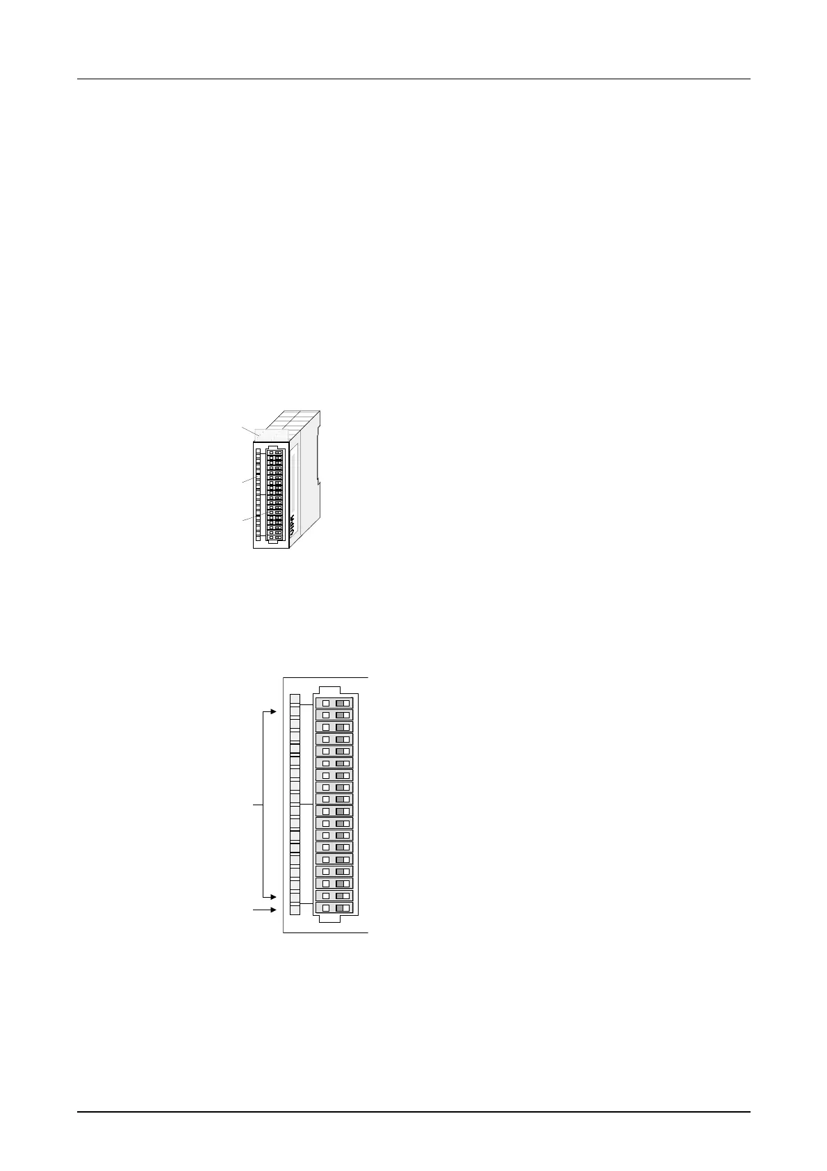
[1]
[2]
[3]
Label for module description
LED status indicator
Edge connector
Assignment
LED
L+
.0...15
F
Description
LED (green)
Supply voltage
available
LEDs (green)
I.0 up to I.15
when the input
signal is "1" or
the output is
active the
respective
LED is turned
on
LED (red)
Overload,
overheat or
short circuit
error
L+
.0
.1
.2
.3
.4
.5
.6
.7
.8
.9
.10
.11
.12
.13
.14
.15
F
1
2
3
4
5
6
7
8
9
10
11
12
13
14
15
16
17
18
+0
Pin
1
2
3
4
5
6
7
8
9
10
11
12
13
14
15
16
17
18
Counter activated Counter
deactivated
Power supply DC 24V
Input Counter (A1) I.0 (byte 3.0)*
Input Counter (B1) I.1 (byte 3.1)
Input Counter (A2) I.2 (byte 7.0)
Input Counter (B2) I.3 (byte 7.1)
Input Counter (A3) I.4 (byte 11.0)
Input Counter (B3) I.5 (byte 11.1)
Input Counter Gate 1 I.6 (byte 12.0)
Input Counter Latch 1 I.7 (byte 12.4)
Input Counter Gate 2 I.8 (byte 12.1)
Input Counter Latch 2 I.9 (byte 12.5)
Input Counter Gate 3 I.10 (byte 12.2)
Input Counter Latch 3 I.11 (byte 12.6)
I/Q.12 Counter out 1 (byte 12.0) / Input (byte 15.0)
I/Q.13 Counter out 2 (byte 12.1) / Input (byte 15.1)
I/Q.14 Counter out 3 (byte 12.2) / Input (byte 15.2)
I/Q.15 Output (byte 12.3) / Input (byte 15.3)
Ground
*) The byte data refer to the offset of the base address of the module.
Properties
Construction
Status indicator
Pin assignment