Chapter 5 238-2BC00 - Combination module Manual VIPA System 200V
5-14 HB97E - SM-AIO - Rev. 12/32
The record set 1 contains the 4byte of record set 0 and additional 8byte
module specific diagnostic data.
The diagnostic bytes have the following assignment:
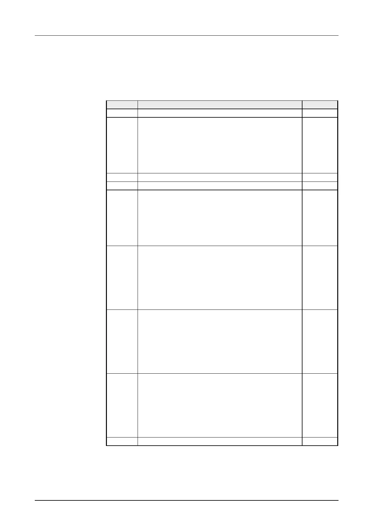
Record set 1 (Byte 0 to 11):
Byte Bit 7 ... Bit 0 Default
0 ... 3 Content record set 0 (see page before) -
4 Bit 6 ... 0: Channel type
70h: Digital input
71h: Analog input
72h: Digital output
73h: Analog output
74h: Analog in-/output
Bit 7: reserved
74h
5 Number of diagnostic bits per channel 04h
6 Number of identical channels of a module 06h
7 Bit 0: Channel error Channel 0
Bit 1: Channel error Channel 1
Bit 2: Channel error Channel 2
Bit 3: Channel error Channel 3
Bit 4: Channel error Channel 4
Bit 5: Channel error Channel 5
Bit 7 ... 6: reserved
00h
8 Bit 0: Wire break Channel 0
Bit 1: Parameterization error Channel 0
Bit 2: Measuring range underflow Channel 0
Bit 3: Measuring range overflow Channel 0
Bit 4: Wire break Channel 1
Bit 5: Parameterization error Channel 1
Bit 6: Measuring range underflow Channel 1
Bit 7: Measuring range overflow Channel 1
00h
9 Bit 0: Wire break Channel 2
Bit 1: Parameterization error Channel 2
Bit 2: Measuring range underflow Channel 2
Bit 3: Measuring range overflow Channel 2
Bit 4: Wire break Channel 3
Bit 5: Parameterization error Channel 3
Bit 6: Measuring range underflow Channel 3
Bit 7: Measuring range overflow Channel 3
00h
10 Bit 0: Wire break at current output res. short circuit
at voltage output Channel 4
Bit 1: Parameterization error Channel 4
Bit 2,3: reserved
Bit 4: Wire break at current output res. short circuit
at voltage output Channel 5
Bit 5: Parameterization error Channel 5
Bit 6,7: reserved
00h
11 reserved 00h
Record set 1
Addition diagnostic
(incoming)