Chapter 5 238-2BC00 - Combination module Manual VIPA System 200V
5-4 HB97E - SM-AIO - Rev. 12/32
Analog part
The analog part has 4 analog inputs and 2 analog outputs that may be
configured individually. The module occupies a total of 8byte of input and
4byte of output data.
Galvanic isolation between the channels on the module and the backplane
bus is provided by means of DC/DC converters and opto couplers.
• 4inputs and 2 outputs with common ground
• In-/Outputs with individually configurable functions
• Channel 0 to 2 suitable for encoder with input ranges of:
voltage ±10V, 1 ... 5V, 0 ... 10V, ±4V, ±400mV
current ±20mA, 4...20mA, 0 ... 20mA
• Channel 3 suitable for encoder with input ranges of:
Pt100, Pt1000, NI100, NI1000
resistant measuring 600Ω, 3000Ω
• Channel 4 to 5 Suitable for actuators with output ranges of:
±10V, 1 ... 5V, 0 ... 10V, ±20mA, 0 ... 20mA or 4 ... 20mA
1
2
[1]
[2]
[3]
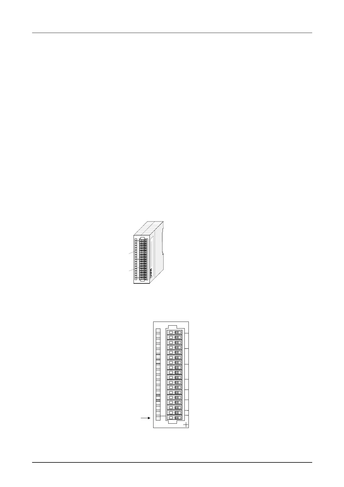
Label for the name of
the module
LED status indicator
Edge connector
LED
F
Description
Sum error LED (red)
turned on as soon as an
channel error is detected
res. an entry in the
diagnostic bytes
happened
1
2
3
4
5
6
7
8
9
10
11
12
13
14
15
16
17
18
VIPA 238-2BC00
X
2
34
SM 238C
F
Pin
1
2
3
4
5
6
7
8
9
10
11
12
13
14
15
16
18
Assignment
DC 24V supply voltage
Voltage measuring channel 0
Current measuring channel 0
Ground channel 0
Voltage measuring Ch. 1
Current measuring Ch. 1
Ground channel 1
Voltage measuring channel 2
Current measuring channel 2
Ground channel 2
Measuring channel 3 (Pt, Ni, R)
Ground 3
Q0 output channel 4
M4 output channel 4
Q1 output channel 5
M5 output channel 5
Ground Supply voltage
Properties
Construction
Status indicator
Pin assignment