Manual VIPA System 200V Chapter 5 238-2BC00 - Combination module
HB97E - SM-AIO - Rev. 12/32 5-5
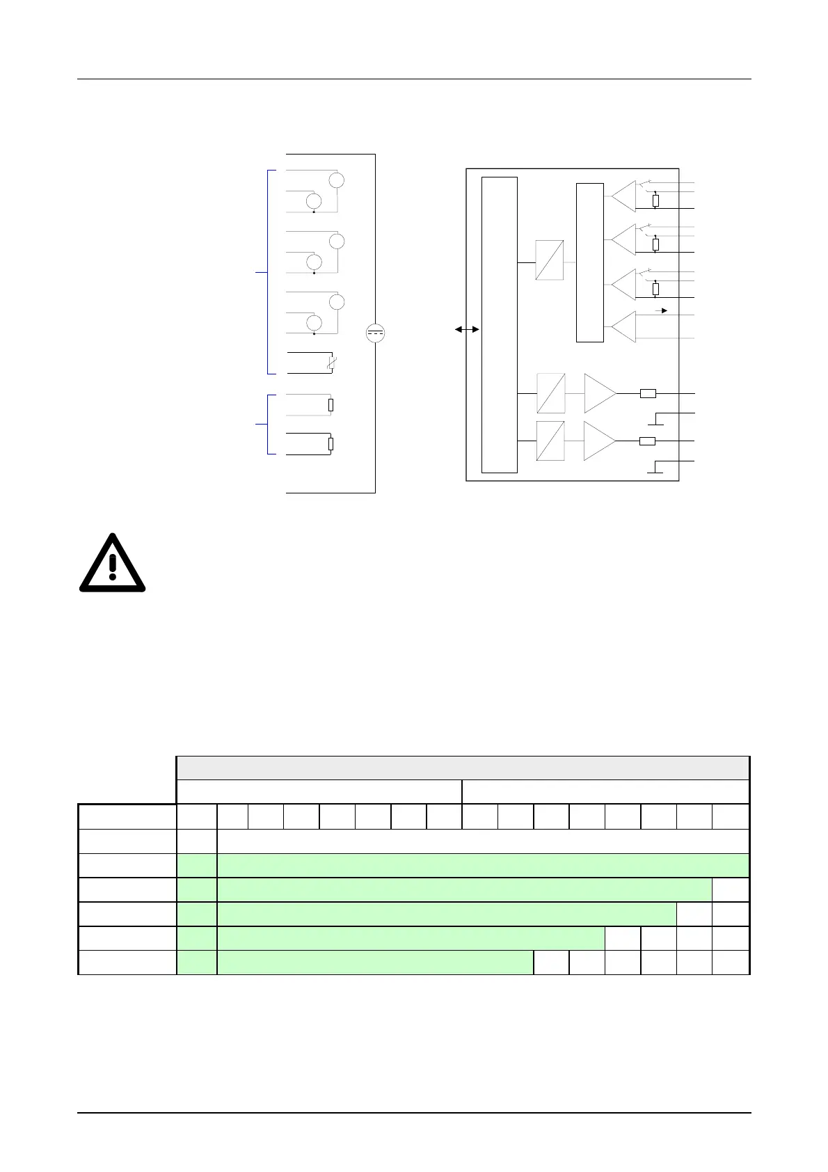
Circuit diagram Schematic diagram
L+
CH1
1
2
3
4
5
14
15
16
17
18
6
7
8
9
10
11
12
13
CH3
CH4
CH5
M
A
V
CH0
A
V
CH2
A
V
DC 24
AI
O
ANA
V-Bus
Input / Output
µP
D
A
Channel 4
Q0
M4
D
A
Channel 0
U0
M0
Mux
Channel 1
I0
M1
I1
U1
Channel 2
M2
I2
U2
M3
Ix
Channel 3
R3
D
A
Channel 5
Q1
M5
33
Ω
33
Ω
33
Attention!
Temporarily not used inputs have to be connected with the concerning
ground at activated channel. When deactivating unused channels by
means of FFh, this is not required.
The analog values are represented in two’s complement format.
Depending on the parameterized transformation speed the lowest value
bits of the measuring value are irrelevant. With increasing sampling rate,
the resolution decreases.
The following table lists the resolution in dependence of the sampling rate.
Analog value
High-Byte Low-Byte
Bit number 15 14 13 12 11 10 9 8 7 6 5 4 3 2 1 0
Resolution sign Measuring value
15 Bit + sign sign Relevant output value (at 3.7 ... 30Hz)
14 Bit + sign sign Relevant output value (at 60Hz) X*
13 Bit + sign sign Relevant output value (at 120Hz) X X
11 Bit + sign sign Relevant output value (at 170Hz) X X X X
9 Bit + sign sign Relevant output value (at 200Hz) X X X X X X
* The lowest value irrelevant bits of the output value are marked with "X".
Bit 15 serves as algebraic sign bit. Here is:
Bit 15 = "0" → positive value
Bit 15 = "1" → negative value
Circuit and
schematic
diagram
Numeric notation
in Siemens
S7 format
Algebraic sign bit
(sign)
 Loading...