Chapter 4 Analog input/output modules Manual VIPA System 200V
4-16 HB97E - SM-AIO - Rev. 12/32
234-1BD60 - AI 4/AO 2x12Bit - Multiin-/output
AI 4/AO 2x12Bit Multiin-/output VIPA 234-1BD60
This module has 4 analog inputs and 2 analog outputs that may be
configured individually. The module occupies a total of 8byte of input and
4byte of output data in the periphery area. Galvanic isolation between the
channels on the module and the backplane bus is provided by means of
DC/DC converters and optocouplers.
• 4inputs and 2 outputs with common ground
• In-/Outputs with individually configurable functions
• Channel 0 to 2 suitable for encoder with input ranges of:
voltage ±10V, 1 ... 5V, 0 ... 10V, ±4V, ±400mV
current ±20mA, 4...20mA or 0 ... 20mA
• Channel 3 suitable for encoder with input ranges of:
Pt100, Pt1000, NI100, NI1000 and
resistant measuring 600
Ω, 3000Ω
• Channel 4 to 5 Suitable for actuators with output ranges of:
±10V, 1 ... 5V, 0 ... 10V, ±20mA, 0 ... 20mA or 4 ... 20mA
1
2
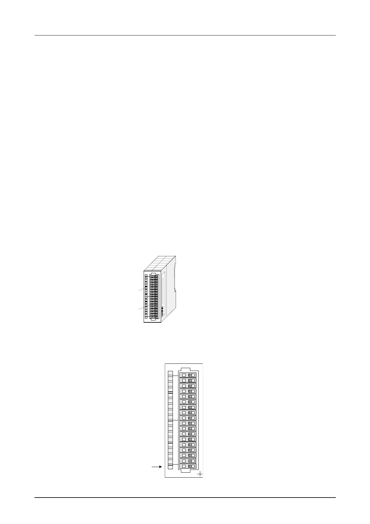
[1]
[2]
[3]
Label for the name of
the module
LED status indicator
Edge connector
LED
SF
Description
Sum error LED (red)
turned on as soon as an
channel error is detected
res. an entry in the
diagnostic bytes
happened
1
2
3
4
5
6
7
8
9
10
11
12
13
14
15
16
17
18
VIPA 234-1BD60
X2
34
AI4/AO2 x12Bit
SF
Pin
1
2
3
4
5
6
7
8
9
10
11
12
13
14
15
16
17
18
Assignment
DC 24V supply voltage
Voltage measuring channel 0
Current measuring channel 0
Ground channel 0
Voltage measuring channel 1
Current measuring channel 1
Ground channel 1
Voltage measuring channel 2
Current measuring channel 2
Ground channel 2
Measuring channel 3 (Pt, Ni, R)
Ground 3
Q0 output channel 4
M4 output channel 4
Q1 output channel 5
M5 output channel 5
reserved
Ground Supply voltage
Order data
Description
Properties
Construction
Status indicator
Pin assignment