Manual VIPA System 200V Chapter 4 Analog input/output modules
HB97E - SM-AIO - Rev. 12/32 4-17
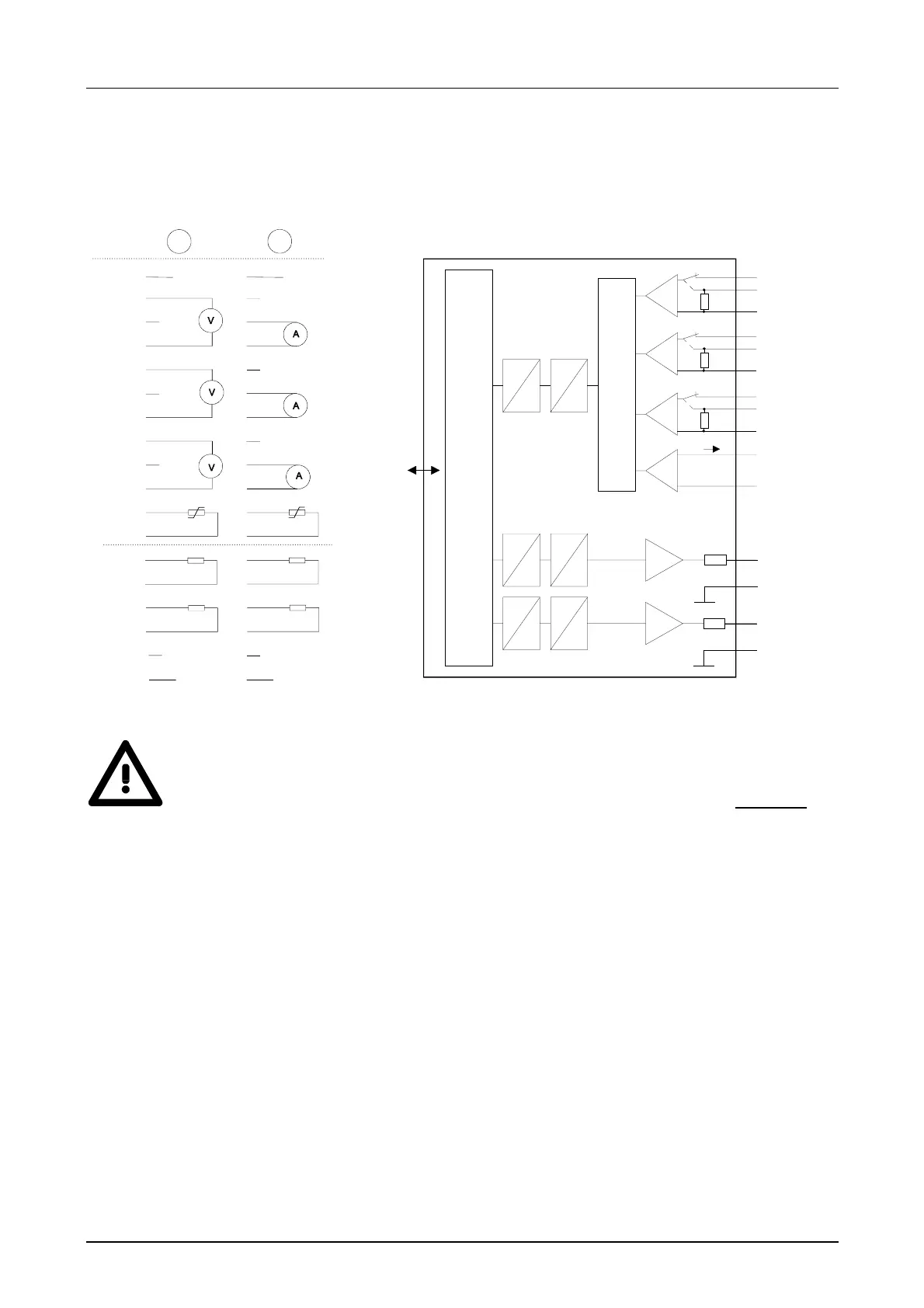
Circuit diagram Schematic diagram
1
2
3
4
5
6
7
8
9
10
1
2
3
4
5
6
7
8
9
10
2
11
12
13
14
15
16
17
11
12
13
14
15
16
17
18
18
1
IN
OUT
Rx Rx
L+ L+
MM
V-Bus
Input / Output
µP
Channel 4
Q0
M4
Channel 0
U0
M0
Mux
Channel 1
I0
M1
I1
U1
Channel 2
M2
I2
U2
M3
Ix
Channel 3
R3
Channel 5
Q1
M5
33
Ω
33
Ω
33
D
A
D
A
D
A
Attention!
The following circumstances may cause damages at the analog module:
• The external supply of the input (current/voltage) must not be
present as long as the backplane bus of the CPU is still without
current supply!
• Parameterization and connection of the input must be congruent!
• You must not apply a voltage >15V to the input!
Circuit and
schematic
diagram