Manual VIPA System 200V Chapter 2 Analog input modules
HB97E - SM-AIO - Rev. 12/32 2-15
231-1BD53 - AI 4x16Bit, multiinput
AI 4x16Bit multiinput VIPA 231-1BD53
The module has 4 inputs that you may configure individually. The module
requires a total of 8 input data bytes in the periphery area (2byte per
channel).
Isolation between the channels on the module and the backplane bus is
provided by means of DC/DC converters and optocouplers.
• the different channels are individually configurable and may be turned off
• the common signal inputs of the channels are not isolated from each
other and the permitted potential difference is up to 5V
• diagnostic function
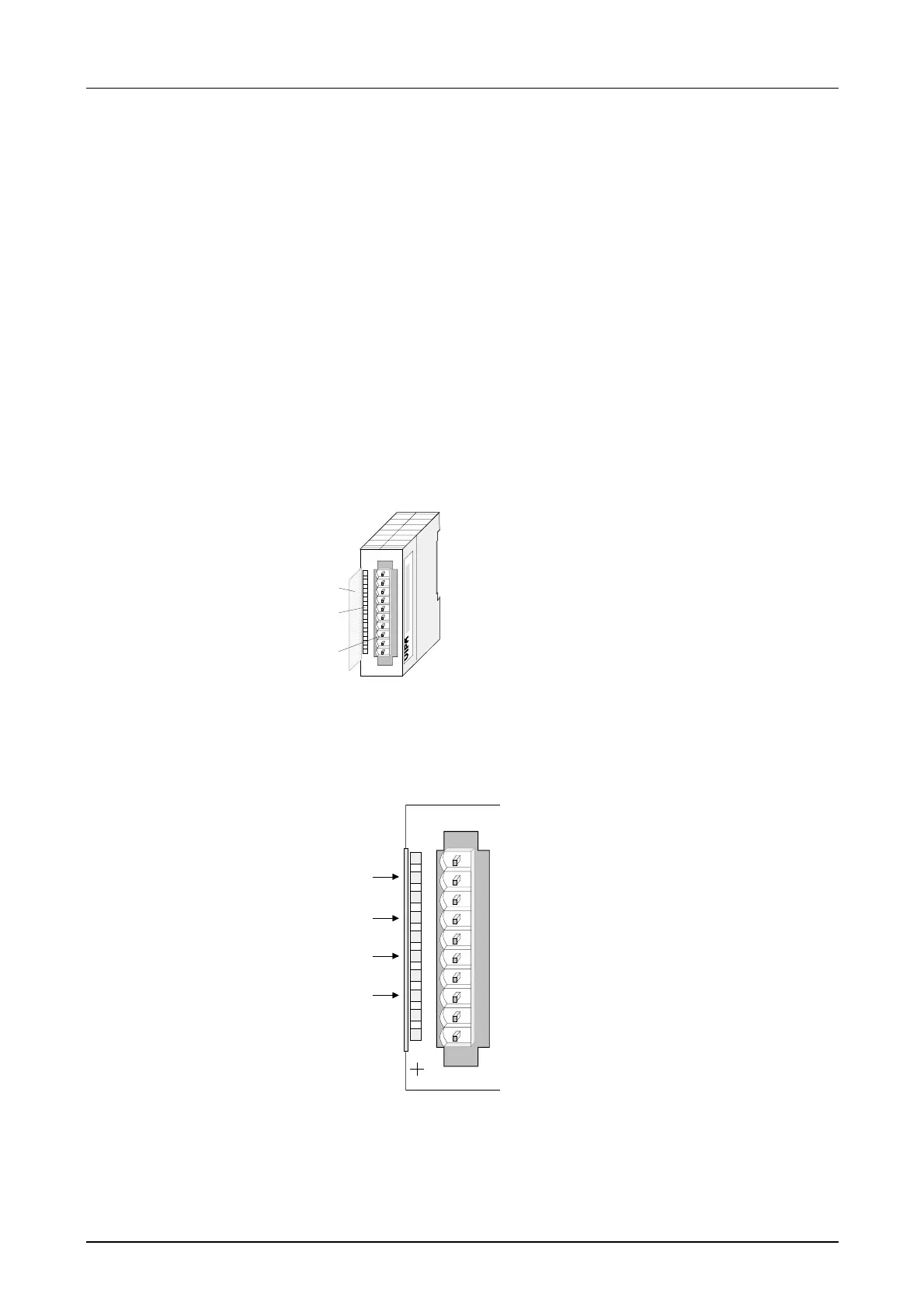
1
[1]
[2]
[3]
Label for the bit address with
description
LEDs
Edge connector
LED
F0 ... F3
Description
LED (red):
turned on as soon as an
channel error is
detected res. an entry in
the diagnostic bytes
happened
AI 4x16Bit
SM 231
F0
F1
F2
F3
VIPA 231-1BD53
X2
34
1
2
3
4
5
6
7
8
9
I0
Pin
1
2
3
4
5
6
7
8
9
10
Assignment
For 4wire systems channel 0
+ channel 0
Channel 0 common
+ channel 1
Channel 1 common
+ channel 2
Channel 2 common
+ channel 3
Channel 3 common
For 4wire systems channel 2
Order data
Description
Properties
Construction
Status indicators
pin assignment