Chapter 2 Analog input modules Manual VIPA System 200V
2-16 HB97E - SM-AIO - Rev. 12/32
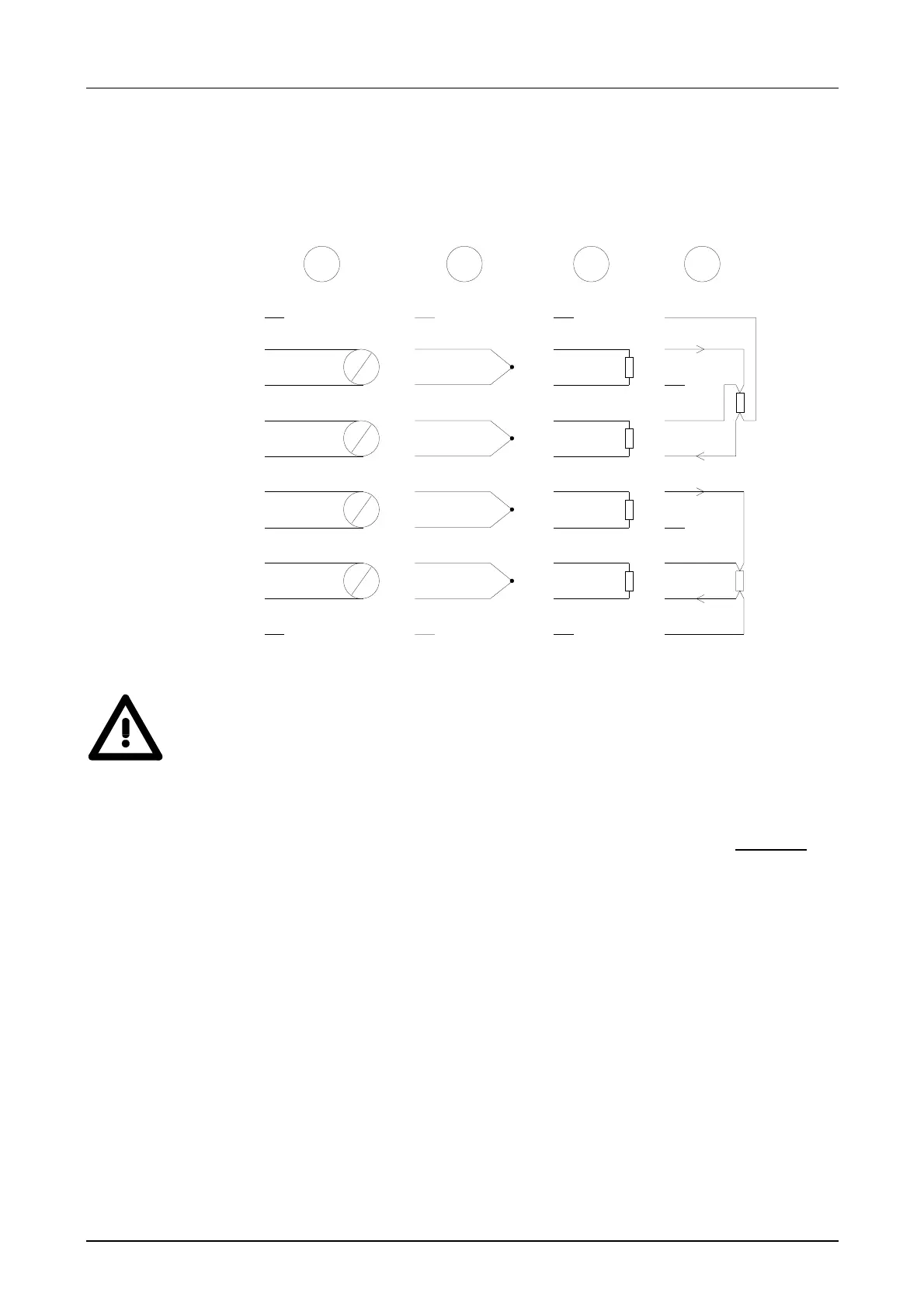
The following illustration shows the connection options for the different
measuring ranges. The assignment to the measuring ranges is to find in the
column "Conn." of the table "Function-no. assignment" on the next pages.
1
2
3
4
5
6
7
8
9
10
V
A
V
A
V
A
V
A
1
2
3
4
5
6
7
8
9
10
1
2
3
4
5
6
7
8
9
10
1
2
3
4
5
6
7
8
9
10
1 2 3 4
U-
U+
I
I
I
I
U-
U+
Attention!
Temporarily not used inputs have to be connected with the concerning
ground at activated channel. When deactivating unused channels by
means of FFh, this is not required.
The following circumstances may cause damages at the analog module:
• The external supply of the input (current/voltage) must not
be
present as long as the backplane bus of the CPU is still without
current supply!
• Parameterization and connection of the input must be congruent!
• You must not apply a voltage >15V to the input!
Wiring diagrams