Chapter 2 Analog input modules Manual VIPA System 200V
2-10 HB97E - SM-AIO - Rev. 12/32
231-1BD40 - AI 4x12Bit 4...20mA, ±
±±
±20mA - ECO
AI 4x12Bit, 4...20mA, ±20mA VIPA 231-1BD40
The module has 4 inputs that you may configure individually. This module
requires a total of 8byte of the process image for the input data (2byte per
channel).
DC/DC converters are employed to provide electrical isolation for the
channels of the module with respect to the backplane bus.
• 4 inputs, channels isolated from the backplane bus
• the different channels are individually configurable and may be turned off
• Suitable for transducers with 4...20mA, ±20mA outputs
• LED leave end overdrive region or leave end underdrive region
or wrong parameterization
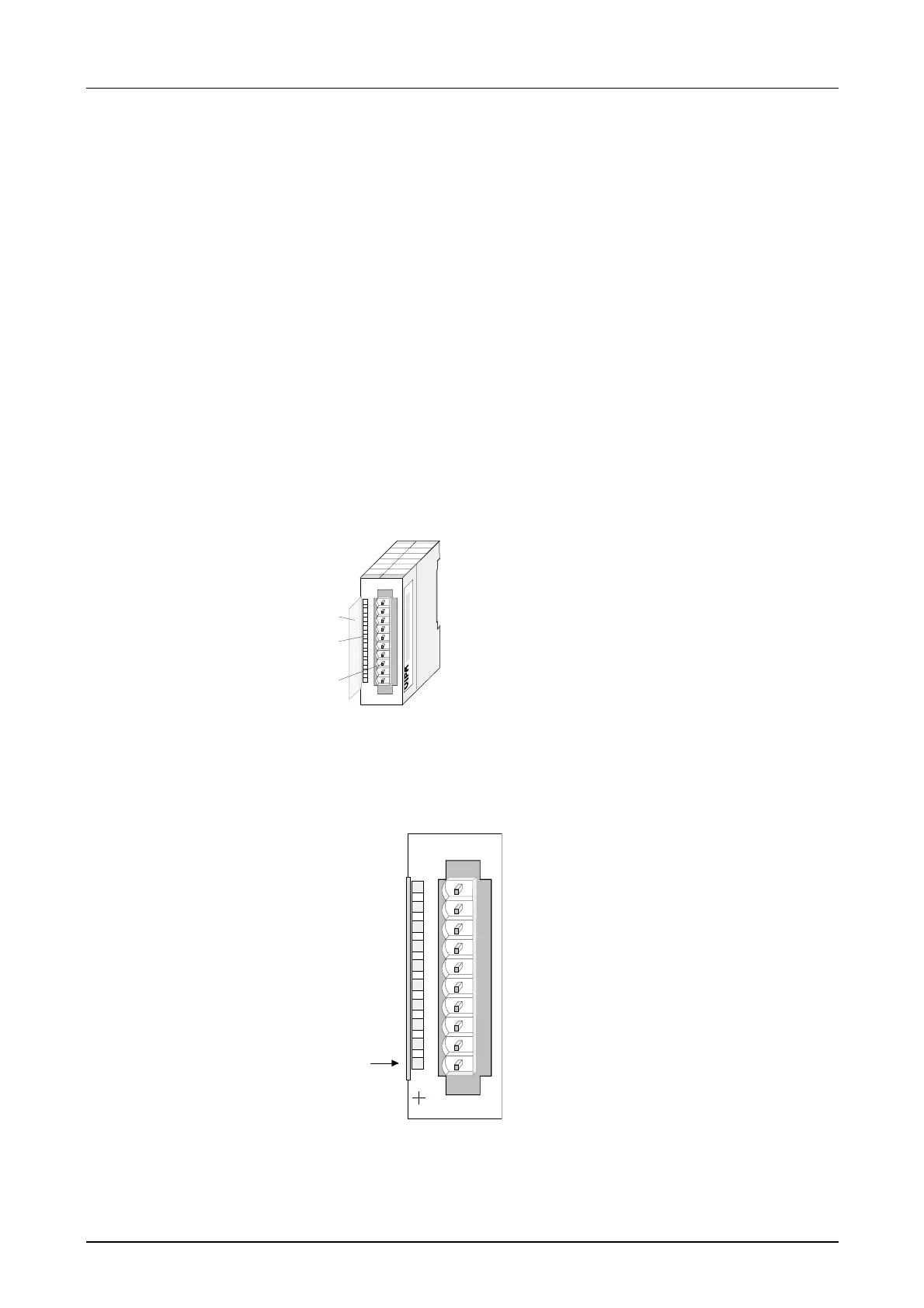
1
[1]
[2]
[3]
Label for the bit address with
description
LED status indicator
Edge connector
LED
SF
Description
LED (red)
Sum error at:
- Leave end of
overdrive region or
leave
end of underdrive
region
- or wrong
parameterization
AI 4x12Bit
SM 231
VIPA 231-1BD40
X2
34
1
2
3
4
5
6
7
8
9
I0
SF
Pin
1
2
3
4
5
6
7
8
9
10
Assignment
pos. connection Ch. 0
Channel 0 common
pos. connection Ch.1
Channel 1 common
pos. connection Ch.2
Channel 2 common
pos. connection Ch.3
Channel 3 common
Order data
Description
Properties
Construction
Status indicator
pin assignment