Manual VIPA System 200V Chapter 5 238-2BC00 - Combination module
HB97E - SM-AIO - Rev. 12/32 5-19
Digital part - Counter - Project engineering
By including the appropriate GSD into your hardware configurator the
module is available via the hardware catalog.
Please take care that you always configure both module parts in the
sequence:
238-2BC00 (1/2) AI4/AO2*12Bit
238-2BC00 (2/2) Counter
You may employ a max. of 2 combination modules at one system!
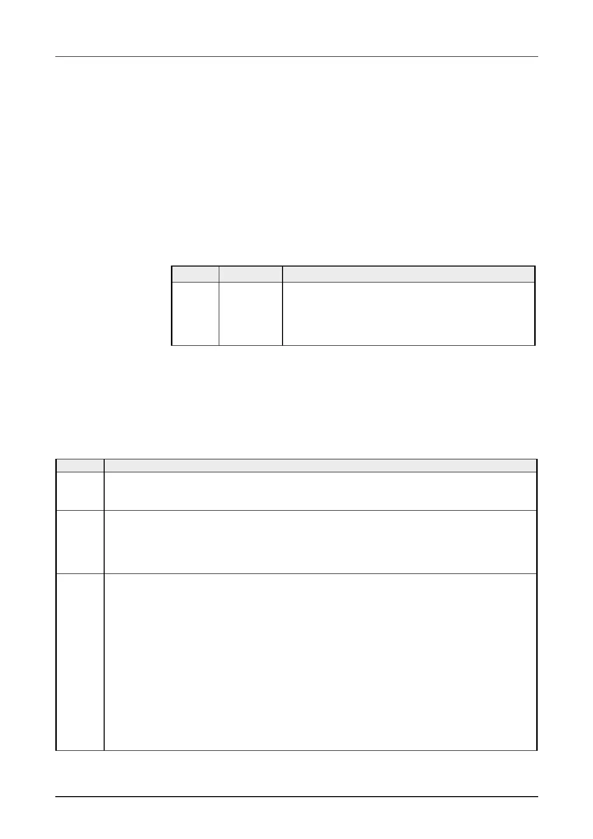
The parameterization happens in the hardware configurator. Here 60Byte
parameter data are transferred:
Byte Record set Description
0 ... 2 0 Basic parameter (Alarm behavior, assignment I/O)
3 ... 21 81h (129) Counter parameter counter 1
22 ... 40 82h (130) Counter parameter counter 2
41 ... 59 83h (131) Counter parameter counter 3
By using SFC 55, 56 and 57 you may alter the parameterization in the
module during runtime. On this occasion 60byte parameter data are stored
at record set 0, 81h, 82h and 83h.
The basic parameters allow you to control the alarm behavior of the digital
part and the assignment of the I/O channels that can be accessed by the
according counter as output.
Byte Description
0 Alarm generation
0 = no
1 = yes
1 Alarm selection
00h = None
01h = Diagnostics
02h = Process alarm
03h = Diagnostics- und Process alarm
2 Assignment of the in-/output channels.
Here you define the assignment of the 4 I/O channels.
If an I/O channel is used as input, you may output the status of the input via Byte 15 of
the input image.
For the operation as output, a detailed definition of the control is required in the
parameter section of the according counter.
Bit 0: 0 = Input I.12
1 = Output Q.12 / Counter output Q.12
Bit 1: 0 = Input I.13
1 = Output Q.13 / Counter output Q.13
Bit 2: 0 = Input I.14
1 = Output Q.14 / Counter output Q.14
Bit 3: 0 = Input I.15
1 = Output Q.15
Overview
Parameterization
Basic parameter
Record set 0