Chapter 2 Analog input modules Manual VIPA System 200V
2-28 HB97E - SM-AIO - Rev. 12/32
231-1BD60 - AI 4x12Bit, 4 ... 20mA, isolated
AI 4x12Bit, 4...20mA, isolated VIPA 231-1BD60
The module has 4 inputs that are permanently configured to measure
current signals (4 ... 20mA). This module requires a total of 8byte of the
process image for the input data (2byte per channel).
The measured values are returned in S5 format from Siemens. DC/DC
converters and isolation amplifiers are employed to provide electrical
isolation for the channels of the module with respect to the backplane bus
and between the different channels.
• 4 inputs, channels isolated from the backplane bus and from each other
(galvanic isolation of the channels by means of isolation amplifiers)
• Permanently configured for current measurements
• No parameterization required
• Suitable for transducers with 4 ... 20mA outputs
• LEDs to indicate wire break
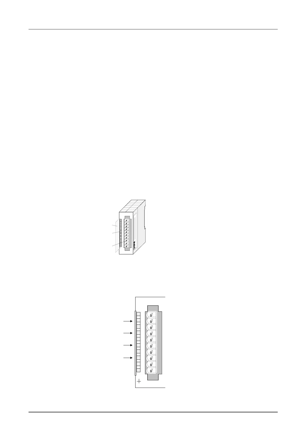
1
[1]
[2]
[3]
Label for the bit address with
description
LED status indicator
Edge connector
LED
+0 ... +3
Description
LED (red)
wire break detection
These LEDs is turned
on when the transducer
is disconnected.
AI 4x12Bit
SM 231
+0
M0
+1
M1
+2
M2
+3
M3
VIPA 231-1BD60
X2
34
1
2
3
4
5
6
7
8
9
I0
Pin
1
2
3
4
5
6
7
8
9
10
Assignment
pos. connection Ch. 0
Channel 0 common
pos. connection Ch.1
Channel 1 common
pos. connection Ch.2
Channel 2 common
pos. connection Ch.3
Channel 3 common
Order data
Description
Properties
Construction
Status indicator
pin assignment