Chapter 5 238-2BC00 - Combination module Manual VIPA System 200V
5-18 HB97E - SM-AIO - Rev. 12/32
The counter is controlled via the internal gate (I-gate). The I-gate is the
result of logic operation of hardware- (HW) and Software-gate (SW), where
the HW-gate evaluation may be deactivated via the parameterization.
HW-gate: Input at Gate
x
-input at module
SW-gate: Open (activate): Output image byte 12, set bit 4 ... 6
depending on counter
Close (deactivate): Output image byte 12, reset bit 4 ... 6
depending on counter
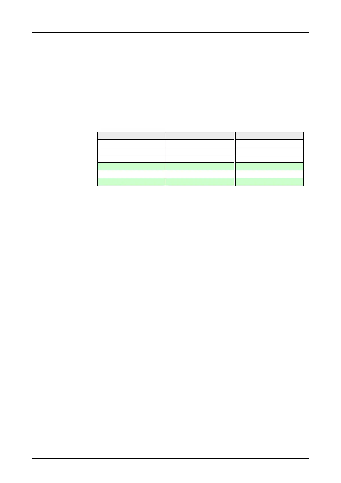
The following states influence the gates:
SW-gate HW-gate influences I-gate
0 0 0
1 0 0
0 1 0
1 1 1
0 deactivated 0
1 deactivated 1
The module sends back a 16byte input image that is mapped into the
memory area of the CPU. Here the current values and states of the counter
can be found among others.
For every counter, the following inputs are available:
Pulse/A (A
x
)
Pulse input for counter signal res. line A of an encoder. Here you may
connect encoders with 1-, 2- or 4-thread evaluation.
Direction/B (B
x
)
Here you connect the direction signal res. line B of the encoder.
You may invert the direction signal by parameterization.
Latch (L
x
)
A positive edge at the digital input „Latch“ stores the recent internal counter
value.
HW Gate (G
x
)
You start the counter via the digital input „Hardware gate“.
Every counter has an assigned output channel. You may set the following
behavior for the according output channel via the parameterization:
• No comparison: Output is not called
• Counter value ≥ comparison value: Output is set
• Counter value ≤ comparison value: Output is set
• Pulse at comparison value: Set output for a configurable pulse duration
Counter start/stop
Access to counter
values via input
image
Counter inputs
(connections)
Counter output