Manual VIPA System 200V Chapter 2 Analog input modules
HB97E - SM-AIO - Rev. 12/32 2-11
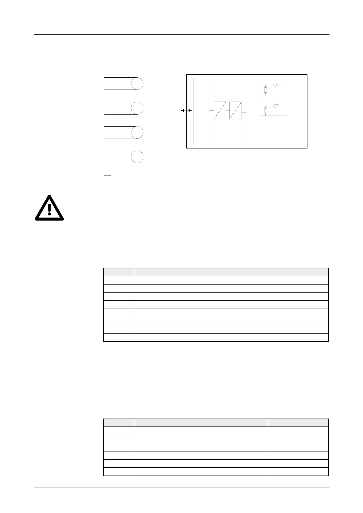
Wiring diagram Schematic diagram
1
2
3
4
5
6
7
8
9
10
A
A
A
A
-Bus
Input
µP
Channel 0
2
3
Mux
Channel 1
4
5
.
.
.
D
A
Attention!
Temporarily not used inputs have to be connected with the concerning
ground at activated channel. When deactivating unused channels by
means of FFh, this is not required.
During a measurement the data is stored in the data input area:
Data input area:
Byte Bit 7 ... Bit 0
0 High-Byte channel 0
1 Low-Byte channel 0
2 High-Byte channel 1
3 Low-Byte channel 1
4 High-Byte channel 2
5 Low-Byte channel 2
6 High-Byte channel 3
7 Low-Byte channel 3
Every channel is individual parameterizable. For the parameterization,
10byte parameterization data are available. The parameterization data are
stored permanently and remain also in off mode. By using the SFC 55
"WR_PARM" you may alter the parameterization in the module during
runtime. The time needed until the new parameterization is valid can last up
to 60ms. During this time, the measuring value output is 7FFFh.
The following table shows the structure of the parameter data:
Parameter area:
Byte Bit 7 ... Bit 0 Default
0, 1 reserved 00h
2 Function-no. channel 0 2Ch
3 Function-no. channel 1 2Ch
4 Function-no. channel 2 2Ch
5 Function-no. channel 3 2Ch
6...9 reserved 00h
Wiring and
schematic
diagram
Measurement data
acquisition
Parameter data