Chapter 5 238-2BC00 - Combination module Manual VIPA System 200V
5-16 HB97E - SM-AIO - Rev. 12/32
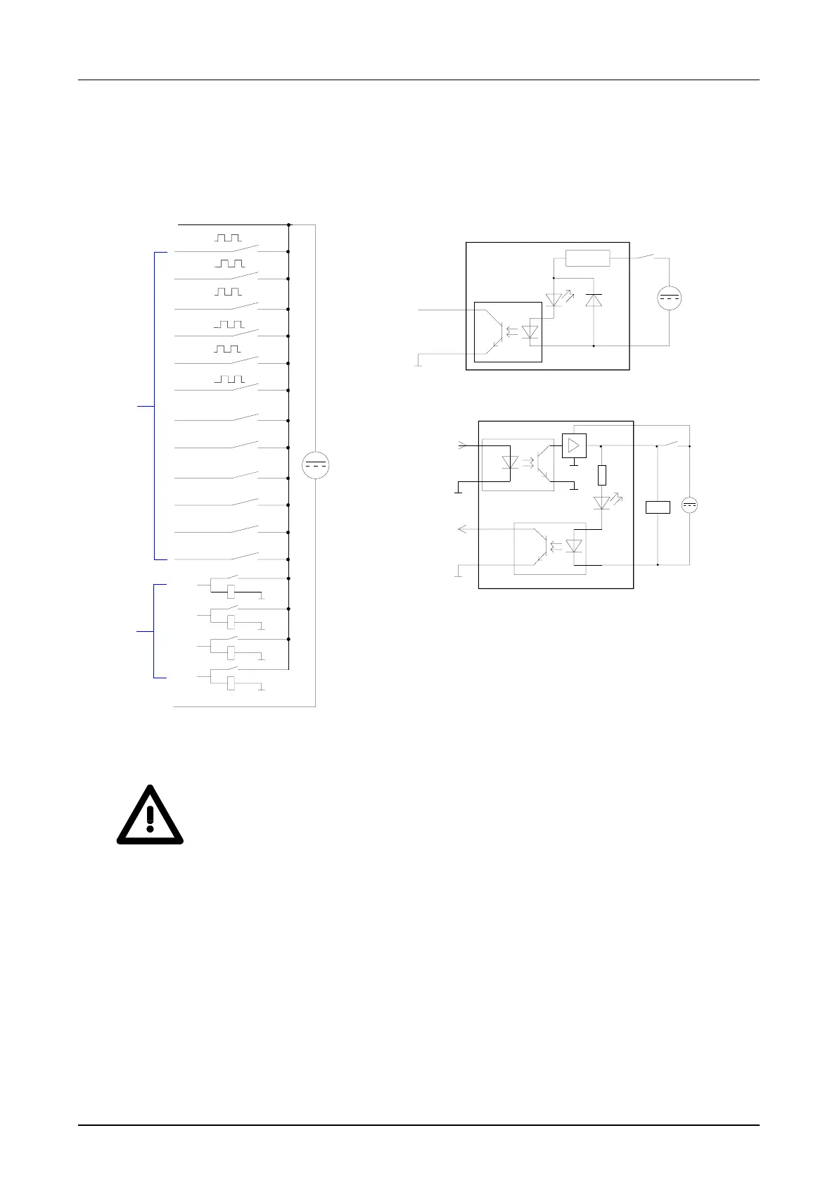
Wiring diagram Schematic diagram
DC 24V
14
15
16
17
18 M
DIO
1
DI
L+
2
3
4
5
6
7
8
9
10
11
12
13
(A1)
(B1)
(A2)
(A3)
(B2)
(B3)
(G1)
(L1)
(G2)
(L2)
(G3)
(L3)
DC 24V
M
intern
V-Bus
Optocoupler
LED
Input module
DC 24V
LED
In-/Out module
M
intern
V-Bus
Optocoupler
Optocoupler
M
intern
Security hints for deploying I/O channels!
Please regard that the voltage applied to an output channel must be ≤ the
voltage supply applied to L+.
Due to the parallel connection of in- and output channel, a set output
channel may be supplied via an applied input signal. Thus, a set output
remains active even at power-off of the voltage supply with the applied
input signal.
Non-observance may cause module demolition.
Wiring and
schematic
diagram