Chapter 4 Analog input/output modules Manual VIPA System 200V
4-4 HB97E - SM-AIO - Rev. 12/32
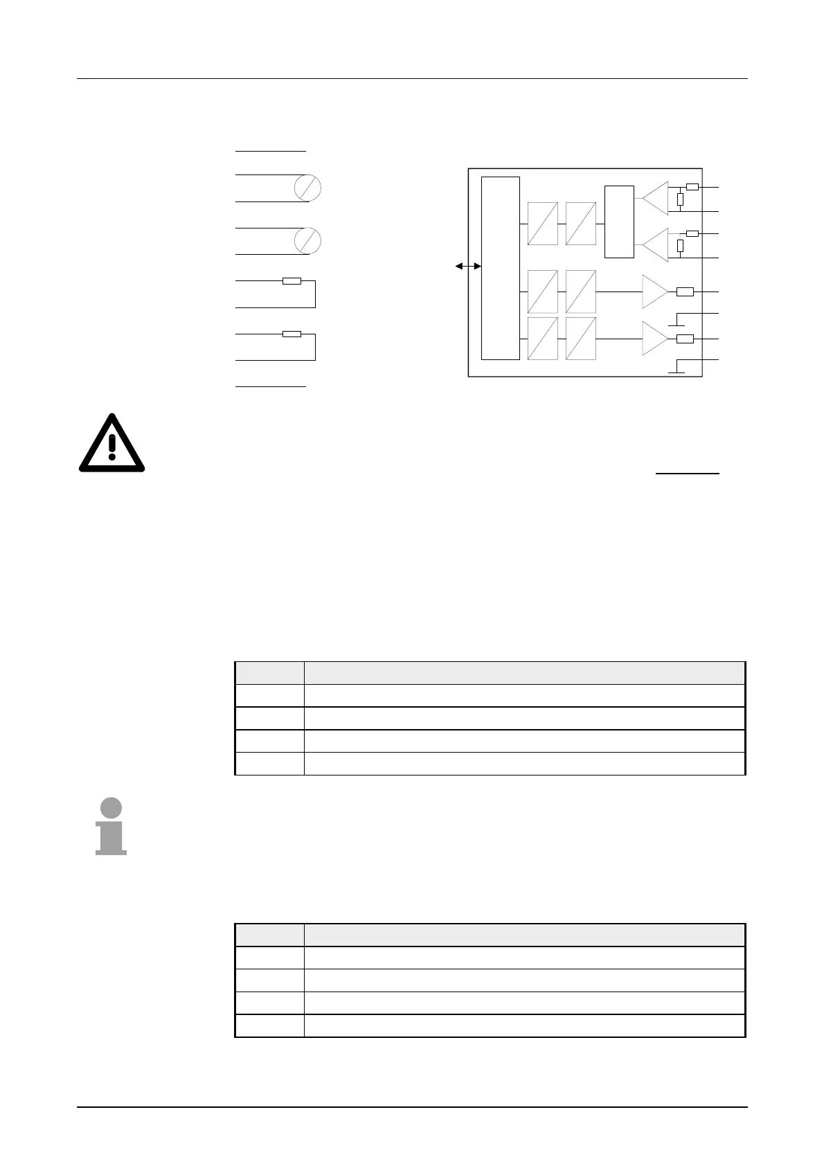
Circuit diagram Schematic diagram
1
2
3
4
5
6
7
8
9
10
L+ DC24V
M
V
A
V
A
IN
IN
OUT
OUT
V-Bus
Input / Output
µP
D
A
Channel
Q1
M1
D
A
Channel
Q0
M0
D
A
Channel
+0
M0
Mux
Channel 1
+0
M1
Attention!
The following circumstances may cause damages at the analog module:
• The external supply of the input (current/voltage) must not be
present as long as the backplane bus of the CPU is still without
current supply!
• Parameterization and connection of the input must be congruent!
• You must not apply a voltage >15V to the input!
Data input range:
During the measuring, the measuring values are stored in the data input
area with the following assignment.:
Byte Bit 7 ... Bit 0
0 High-Byte channel 0
1 Low-Byte channel 0
2 High-Byte channel 1
3 Low-Byte channel 1
Note!
At 3wire res. 4wire measuring, only channel 0 is used.
Data output range:
For output of the data you set a value in the data output area. The
functionality can be set by means of function-no. for each channel.
Byte Bit 7 ... Bit 0
0 High-Byte channel 2
1 Low-Byte channel 2
2 High-Byte channel 3
3 Low-Byte channel 3
Circuit and
schematic
diagram
Data input/
data output range