Manual VIPA System 200V Chapter 4 Analog input/output modules
HB97E - SM-AIO - Rev. 12/32 4-5
12byte of parameter data are available for the configuration. These
parameters are stored in non-volatile memory and are available after the
unit has been powered off.
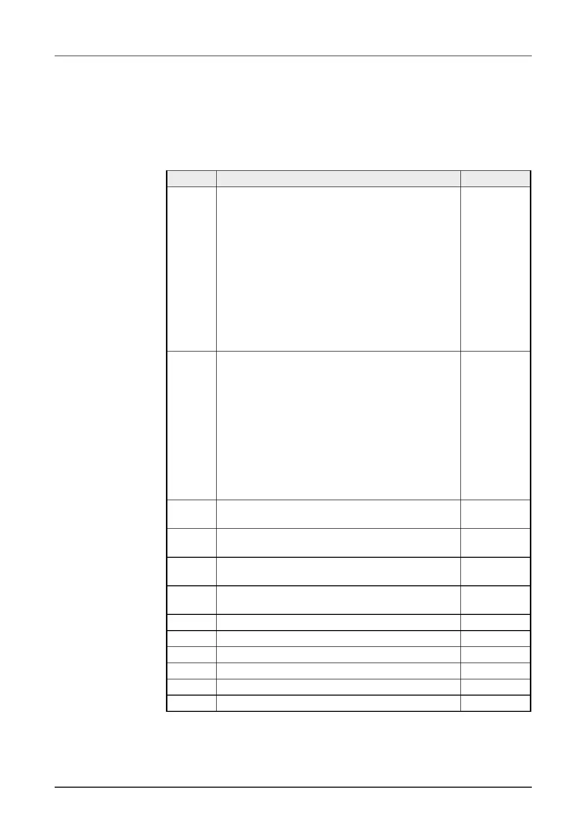
The following table shows the structure of the parameter data:
Parameter area:
Byte Bit 7 ... Bit 0 Default
0 Wire break recognition and diagnostic interrupt:
Bit 0: Wire break recognition channel 0
0: deactivated
1: activated
Bit 1: Wire break recognition channel 1
0: deactivated
1: activated
Bit 5 ... 2: reserved
Bit 6: 0: diagnostic interrupt inhibited
1: diagnostic interrupt enabled
Bit 7: reserved
00h
1 reserved
Bit 0: reserved
Bit 1: reserved
Bit 2: CPU-Stop reaction for channel 2
0: Set replacement value channel 2
*)
1: Store last value channel 2
Bit 3: CPU-Stop reaction for channel 3
0: Set replacement value channel 3
1: Store last value channel 3
Bit 7 ... 4: reserved
00h
2 Function-no. channel 0
(see table input ranges)
28h
3 Function-no. channel 1
(see table input ranges)
28h
4 Function-no. channel 2
(see table input ranges)
09h
5 Function-no. channel 3
(see table input ranges)
09h
6 Meas. cycle channel 0 00h
7 Meas. cycle channel 1 00h
8 High-Byte replacement value channel 2 00h
9 Low-Byte replacement value channel 2 00h
10 High-Byte replacement value channel 3 00h
11 Low-Byte replacement value channel 3 00h
*)
If you want to get 0A res. 0V as output value at CPU-STOP, you have to set the following
replacement values at current output (4...20mA) res. voltage output (1...5V):
E500h for the S7 format from Siemens and F000h for the S5 format from Siemens.
Parameter data