Chapter 2 Analog input modules Manual VIPA System 200V
2-40 HB97E - SM-AIO - Rev. 12/32
During a measurement, the data is stored in the data input area. The table
above shows the allocation of the data to a measured value as well as the
respective tolerance.
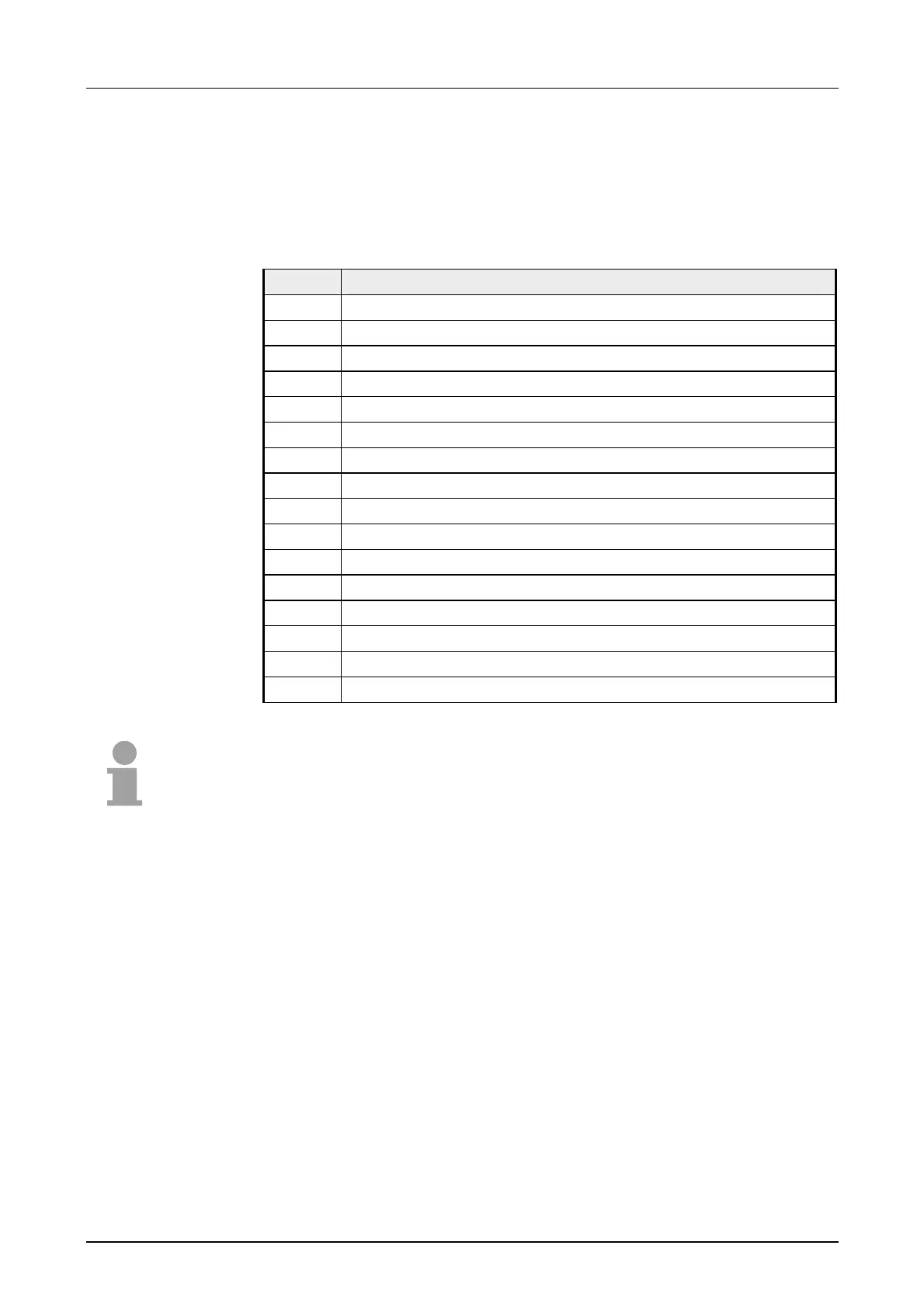
The following figures show the structure of the data input area:
Data input area:
Byte Bit 7 ... Bit 0
0 High-Byte channel 0
1 Low-Byte channel 0
2 High-Byte channel 1
3 Low-Byte channel 1
4 High-Byte channel 2
5 Low-Byte channel 2
6 High-Byte channel 3
7 Low-Byte channel 3
8 High-Byte channel 4
9 Low-Byte channel 4
10 High-Byte channel 5
11 Low-Byte channel 5
12 High-Byte channel 6
13 Low-Byte channel 6
14 High-Byte channel 7
15 Low-Byte channel 7
Note!
Only channels 0, 2, 4 and 6 are used in 4wire systems.
Measurement data
acquisition
 Loading...