Chapter 2 Analog input modules Manual VIPA System 200V
2-48 HB97E - SM-AIO - Rev. 12/32
LED
F0
...
F3
Description
LED (red):
is on if the measured
current value exceeds
the range 4...20mA
(cable break or
overload).
F0
F1
F2
F3
1
2
3
4
5
6
7
8
9
10
11
12
13
14
15
16
17
18
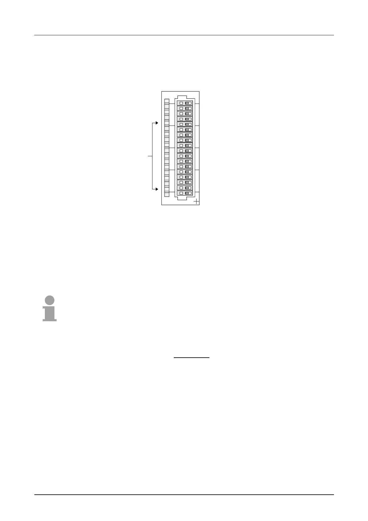
VIPA 231-1FD00
X2
34
AI 4x16Bit f
Pin
1
2
3
4
5
6
7
8
9
10
11
12
13
14
15
16
17
18
Assignment
L+ (In)
+2.5V
pos. connection channel 0
neg. connection channel 0
L+ (Out)
+2.5V
pos. connection channel 1
neg. connection channel 1
L+ (Out)
+2.5V
pos. connection channel 2
neg. connection channel 2
L+ (Out)
+2.5V
pos. connection channel 3
neg. connection channel 3
L+ (Out)
GND
Note!
Unused inputs on activated channels have to be connected to the respec-
tive ground. This is not necessary when the unused channels are turned off
by means of FFh.
The following circumstances may cause damages at the analog module:
• The module must always first
be power supplied via backplane bus
before connecting the external power supply (current/voltage) to the
front connector.
• Parameterization and connection of the input must always be congruent!
• You must not apply a voltage >15V to the input!
Status indicator
pin assignment