Chapter 3 Analog output modules Manual VIPA System 200V
3-8 HB97E - SM-AIO - Rev. 12/32
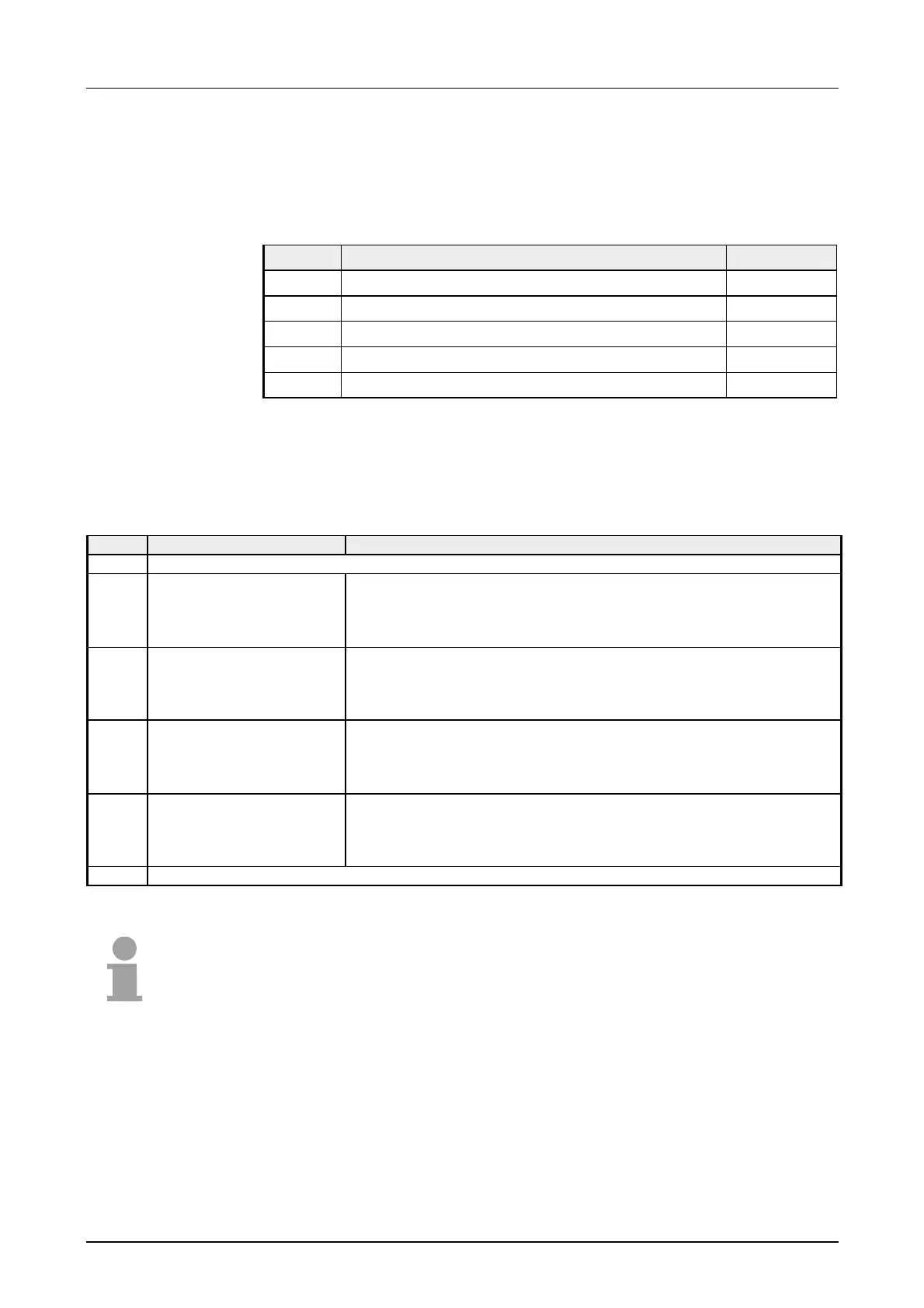
6byte of parameter data are available for the configuration data. These
parameters are stored in non-volatile memory and are available after the
unit has been powered off.
The following table shows the structure of the parameter data:
Parameter area:
Byte Bit 7 ... Bit 0 Default
0, 1 reserved 00h
2 Function-no. channel 0 09h
3 Function-no. channel 1 09h
4 Function-no. channel 2 09h
5 Function-no. channel 3 09h
The assignment of a function-no. to a certain channel happens during
parameterization. The function-no. 00h does not influence the function-no.
stored in the permanent parameterization data.
Assigning FFh deactivates the according channel.
No. Function Output range
00h Does not affect permanently stored configuration data
01h
Voltage
±10V
Siemens S5 format
(two's complement)
±12.5V
12.5V = max. value before over range (20480)
-10...10V = rated range (-16384...16384)
-12.5V = min. value before under range (-20480)
05h Voltage 0...10V
Siemens S5 format
(two's complement)
0...12.5V
12.5V = max. value before over range (20480)
0...10V = rated range (0...16384)
no under range available
09h
Voltage
±10V
Siemens S7 format
(two's complement)
±11.76V
11.76V= max. value before over range (32511)
-10V...10V = rated range (-27648...27648)
-11.76 = min. value before under range (-32512)
0Dh Voltage 0...10V
Siemens S7 format
(two's complement)
0...11.76V
11.76V = max. value before over range (32511)
0...10V = rated range (0...27648)
no under range available
FFh Channel not active (turned off)
Note!
• The module is preset to the range "±10V voltage"
in S7-format from
Siemens.
• When cross over or underdrive range all modes return the value 0.
Parameter data
Function-no.
allocation