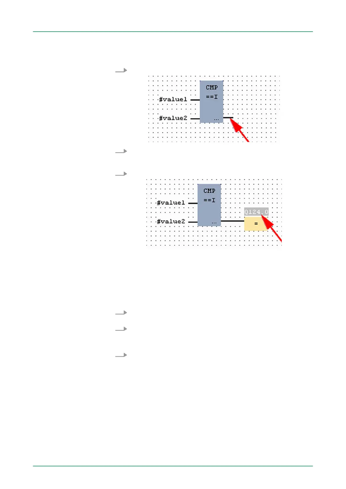
The allocation to the corresponding output, here Q 124.0, takes place
with the following proceeding:
1. Click to the output at the right side of the operator.
2. Open in the catalog the category ‘Bit logic’ and select the func-
tion ‘--[=]’ . The inserting of ‘--[=]’ corresponds to the WinPLC7
shortcut [F7].
3. Insert the output Q 124.0 by clicking to the operand.
ð
Network1 is finished, now.
Adding a new network
For further comparisons the operations "CMP>I" at Q 124.1 and
"CMP<I" at Q 124.2 are necessary. Create a network for both opera-
tions with the following proceeding:
1. Move your mouse at an arbitrary position on the editor window
and press the right mouse key.
2.
Select at ‘context menu è Insert new network’.
ð
A dialog field is opened to enter the position and number of
the networks.
3. Proceed as described for "Network 1".
VIPA System 300SWinPLC7
Example project engineering > Project engineering
HB140 | CPU-SC | 312-5BE13 | GB | 15-50 172