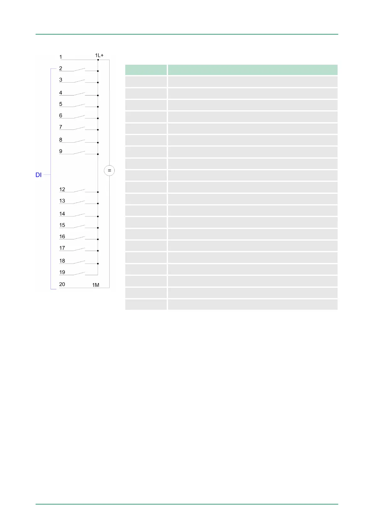
Pin assignment X11: DI
Pin Assignment
1 1L+ Power supply +DC 24V
2 I+0.0 / Channel 0 (A) / Pulse
3 I+0.1 / Channel 0 (B) / Direction
4 I+0.2 / Channel 0 HW gate
5 I+0.3 / Channel 1 (A) / Pulse
6 I+0.4 / Channel 1 (B) / Direction
7 I+0.5 / Channel 1 HW gate
8 I+0.6
9 I+0.7
10 not used
11 not used
12 I+1.0
13 I+1.1
14 I+1.2
15 I+1.3
16 I+1.4 / Channel 0 Latch
17 I+1.5 / Channel 1 Latch
18 I+1.6
19 I+1.7
20 Ground 1M DI
VIPA System 300S Hardware description
Structure > In-/Output area CPU 312-5BE13
HB140 | CPU-SC | 312-5BE13 | GB | 15-50 29