2.28 - GRIPPER ADJUSTMENT
Schematics & Parts mySelective.com
CHAPTER 2 41
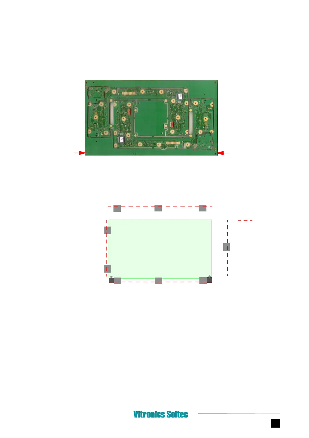
2.28.4.3 PCB METHOD
In the PCB and in the Coldplate two pin positioning holes are placed for correct positioning of
the PCB in the gripper.
FIGURE 2.52 PCB
F
IGURE 2.53 GRIPPER ADJUSTMENT WITH PCB
1. Open gripper.
2. Slide rail 3 and 4 to its outer position.
3. Measure the width and length of the PCB.
4. Adjust grippers 1a and b equally divided over the PCB width.
5. Adjust grippers 2a, b and c equally divided over the PCB length.
6. Hold PCB in gripper against rail 1 and 2 and fine adjust the pin positionings 2d and 2e
together with grippers 2a and 2c.
PIN
POSITIONING
HOLE
IN
PCB (2
X
)
BOTTOMVIEW
GRIPPERS
PIN
POSITIONING
PIN
POSITIONING
PCB
IN
GRIPPER
=
RAIL
❶
❸
❷
❹
a
a
a
a
b
c
b
c
d
e