PARTS
42 CHAPTER 2
7. Slide rail 3 against the PCB and keep a small space (± 0.3 mm) between the grippers 3a,b,c
and the PCB.
8. Slide rail 4 against the PCB and keep also a small space (± 0.3 mm) between the gripper 4a
and the PCB.
9. Close gripper and check if PCB is correctly in position and correct if necessary.
10. Open gripper and take out the PCB.
11. Gripper ready for use in machine.
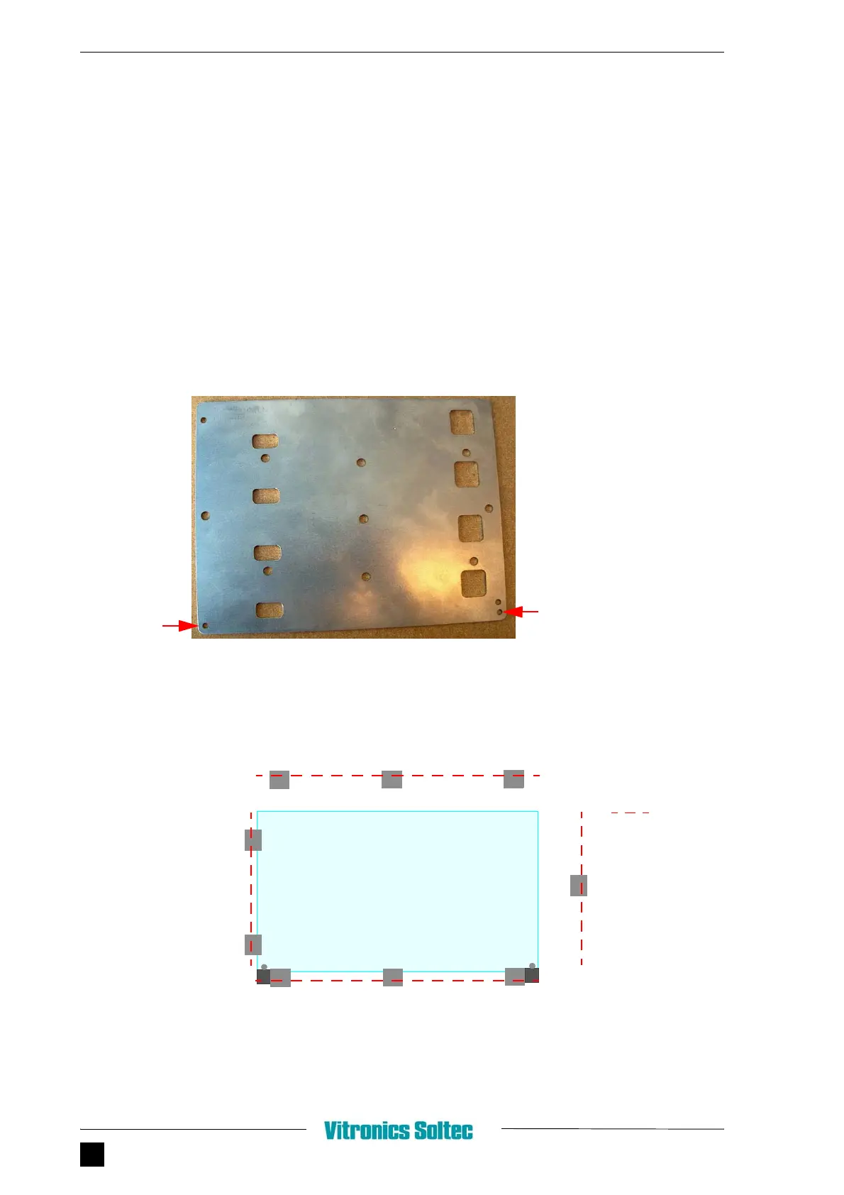
2.28.4.4 COLDPLATE METHOD
FIGURE 2.54 COLDPLATE
FIGURE 2.55 GRIPPER ADJUSTMENT WITH COLDPLATE
PIN
POSITIONING
HOLE
IN
C
OLDPLATE
(2
X
)
BOTTOMVIEW
GRIPPERS
PIN
POSITIONING
PIN
POSITIONING
C
OLDPLATE
IN
GRIPPER
=
RAIL
❶
❸
❷
❹
a
a
a
a
b
c
b
c
d
e