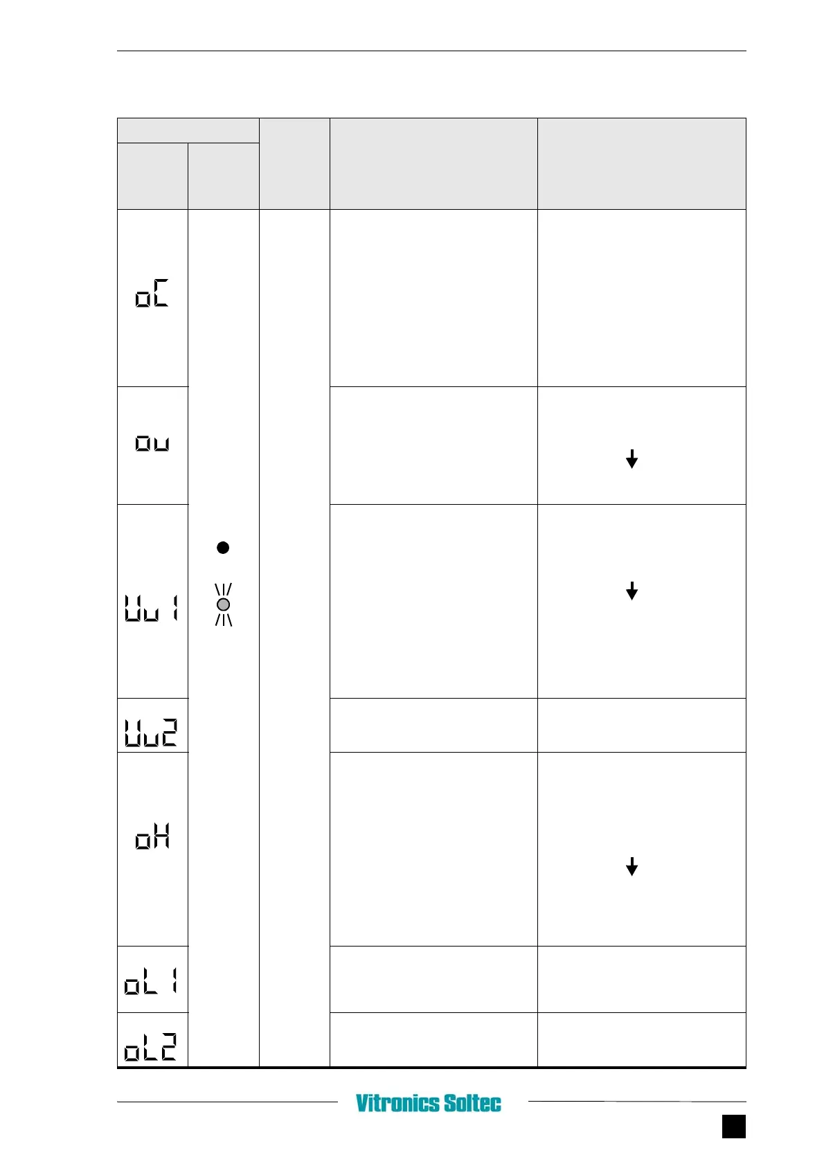
3.3 - FREQUENCY INVERTER
Schematics & Parts mySelective.com
CHAPTER 3 5
Protective
Operation
Output is
shut OFF
and motor
coasts to a
stop
OC (overcurrent)
Inverter output current momentarily
exceeds approx. 250% of rated current
Check the following and restart:
• Short-circuit or grounding at
inverter output side
• Excessive load GD²
• Extremely rapid accel/decel time
(n019 to n022)
• Special motor used
• Starting motor during coasting
• Motor of a capacity greater than the
inverter rating has been started
• Magnetic contactor open/closed at
the inverter output side
OV (main circuit overvoltage)
Main circuit DC voltage exceeds the
overvoltage detection level due to
excessive regenerative energy from the
motor. Detection level
200V class: approx. 410V and more
400V class: approx. 820V and more
• Insufficient decel time (constants
n020 and n022)
• Large minus load at lowering
(elevator, etc.)
• Increase decel time
• Connect optional braking resistor
UVI (main Circuit low-voltage)
Main Circuit DC voltage drops below the
low-voltage detection level while inverter
output is ON.
Detection level
200V class: approx. 200V and less (approx.
160V and less for single-phase)
400V class: approx. 400V and less
• Reduction of input power supply
voltage
• Open phase of input supply
• Occurrence or momentary power
loss
Check the following:
• Power supply voltage
• Main circuit power supply wiring is
connected
• Terminal screws are securely
tightened
UV2 (control power supply fault)
Voltage fault of control power supply is
detected
Turn OFF, and ON power. If fault remains,
replace the inverter
OH (cooling fin overheat)
Temperature rise due to inverter overload
operation or intake air temperature rise
• Excessive load
• Improper V/f pattern setting
• Insufficient accel time if the fault
occurs during acceleration
• Intake air temperature exceeding
50°C
• Cooling fan is stopped
Check the following:
• Load size
• V/f pattern setting (n011 to n017)
• Intake air temperature
OL1 (motor overload)
Motor overload protection activated by
built-in electronic thermal overload relay
• Check the load size and V/f pattern
setting (n011 to n017)
• Set n036 to the rated current on
motor nameplate
OL2 (inverter overload)
Inverter overload protection activated by
built-in electronic thermal overload relay
• Check the load size and V/f patter
setting (n011 to n017)
• Check the inverter capacity
ALARM DISPLAY
INVERTER
STATUS
EXPLANATION CAUSES AND
CORRECTIVE ACTIONS
DIGITAL
OPERATOR
RUN
(GREEN)
ALARM
(RED)