CONFIDENTIAL
–
DO NOT COPY Page 7-9
File No. SG-0204
2. DIGITAL AUDIO INTERFACE
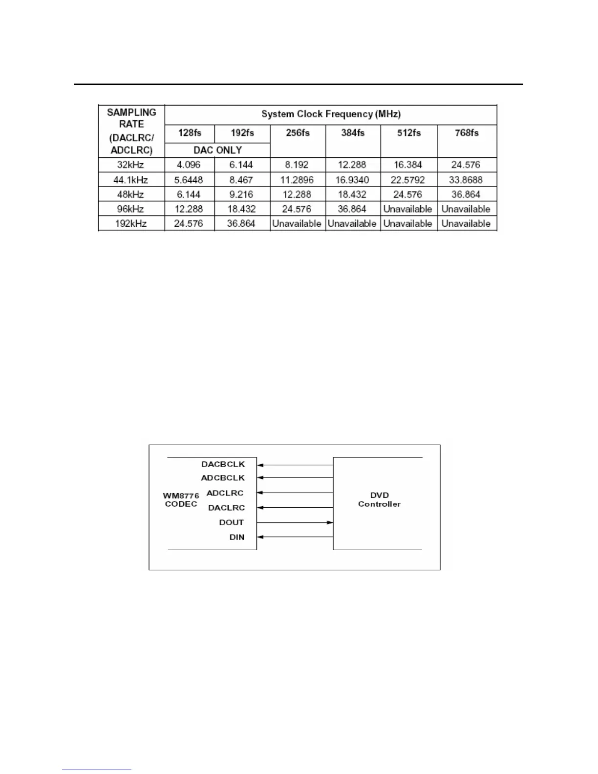
1. Slave mode
The audio interfaces operations in either slave mode selectable using the MS control bit. In
slave mode DIN is always an input to the WM8776 and DOUT is always an output. The default
is Slave mode. In slave mode (ms=0) ADCLRC, DACLRC, ADCBCLK, DACBCLK are input to
the WM8776
DIN and DACLRC are sampled by the WM8776 on the rising edge of DACBCLK;
ADCLRC is sampled on the rising edge of ADCBCLK. ADC data is output on DOUT and
changes on the falling edge of ADCBCLK. By setting control bit BCLKINV the polarity of
ADCBCLK and DACBCLK may be reversed so that DIN and DACLRC are sample on the
falling edge of DACBCLK, ADCLRC is sampled on the falling edge of ADCBCLK and DOUT
changes on the rising of ADCBCLK Slave mode
as shown in the following figure.
2. 2 Wire serial control mode
The wm8776 supports software control via a 2-wire serial bus. Many devices can be controlled
by the same bus, and each device has a unique 7-bit address (this is not the same as the 7-bit
address of each register in the wm8776). The wm8776 operates as a slave device only.
2-wire serial interface as shown in the following figure.
 Loading...