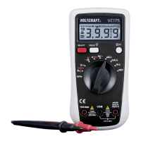
If the measuring range is exceeded, an overload is displayed. This display is model-dependent and signalled
with “I” in the VC 130-1 and VC150-1 and with “OL” in the VC170-1. Select the next-higher measuring range.
The voltage range „V/DC“ has an input resistance of >10 MOhm, the V/AC range of >4.5 MOhm
With the VC170-1, the automatic range selection (auto range) is active in all measuring functions (except for
currency measuring ranges). This function sets the right measuring range automatically.
Before measuring voltages, always make sure that the measuring instrument is not set to a measuring range for
currents.
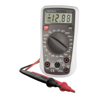
Measuring socket selection and assignment of the black and red measuring cable
DMM black red
VC130-1 COM (5) V (8)
VC150-1 COM (5) V (8)
VC170-1 COM (5) V (8)
- Turn the DMM on (VC130-1/150-1 on the “POWER” switch (3) and the VC170-1 on the rotary switch). Select the
measuring range “V
”.
- Insert the measuring cables into the corresponding measuring sockets as shown in the table.
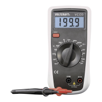
- Now connect the two measuring prods to the object to be measured (battery, switch etc.).
The red measuring tip indicates the positive pole, the black measuring tip the negative pole.
- The polarity of the respective measuring value is indicated on the together with the current measuring value.
As soon as a minus “-” appears for the direct voltage in front of the measuring value, the measured voltage is
negative (or the measuring tips have been mixed up).
- After measuring, remove the measuring leads from the measuring object and turn the DMM off. Turn the rotary
switch to the position “OFF” or turn the device off via the “POWER” switch.