.
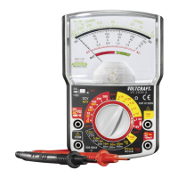
Measuring socket selection and assignment of the black and red measuring cable
DMM black red
VC130-1 COM (5) mA/Ω (7)
VC150-1 COM (5) mA/Ω (7)
VC170-1 COM (5) V/Ω (8)
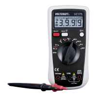
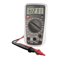
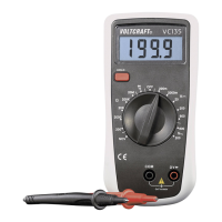
- Turn the DMM on and select measuring range
- Insert the measuring cables in line with the model into the corresponding measuring sockets as shown in the
table.
- To activate the acoustic continuity tester function, press the button “SELECT” (3). Pressing this button again takes
you back to the rst measuring function (diode test) etc.
- A measuring value of approx. < 10 Ohm is detected for the throughput and a permanent signal sounds.
- If “overload” appears on the display, you have exceeded the measuring range or the measuring circuit is inter-
rupted.
- After measuring, remove the measuring leads from the measuring object and turn the DMM off. Turn the rotary
switch to the position “OFF” or turn the device off via the “POWER” switch.
- Turn the DMM on and select measuring range “NCV”
- Test this function beforehand on a known AC voltage source.
- Guide the measuring device with the sensor area (1) towards to position to be tested at a distance of max. 10 mm.
In case of twisted cables, it is recommended to check the cable at a length of approx. 20 to 30 cm.
- An acoustic signal sounds during voltage recognition. The display is not needed for this and shows no dened
values.
- After you nish measuring, turn the DMM off. Turn the rotary switch to the position “OFF” or turn the device off via
the “POWER” switch.
Due to the sensitivity, static elds may also be displayed when touching. This is normal and does not inu-
ence the test result.