Measuring socket selection and assignment of the black and red measuring cable
DMM black red
VC130-1 COM (5) mA/Ω (7)
VC150-1 COM (5) mA/Ω (7)
VC170-1 COM (5) V/Ω (8)
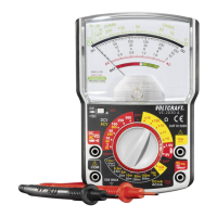
- Turn the DMM on and select measuring range
- Insert the measuring cables in line with the model into the corresponding measuring sockets as shown in the
table.
- Check the measuring leads for continuity by connecting both measuring prods to one another. After that the value
must be approximately 0 V. The open-circuit voltage is approx. 3 V.
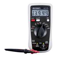
- Now connect the two measuring prods with the object to be measu-red (diode).
- The display shows the continuity voltage in volt (V).
- If the symbol for “overload” is shown the diode is measured in the locking direction
or the diode is defective (interruption). Perform a counter-pole measuring for control
reasons. The red measuring lead corresponds to the positive pole (anode), the black
measuring lead to the negative pole (cathode). A silicone diode has an on-state volt-
age of approx. 0.5 – 0.8 V.
- After measuring, remove the measuring leads from the measuring object and turn the DMM off. Turn the rotary
switch to the position “OFF” or turn the device off via the “POWER” switch.