- Put the DMM into operation as described in the section “Measuring of direct voltage” and select the measuring
range “V “
“AC” appears on the display.
- Now connect the two measuring prods to the object to be measured (generator, switch etc.).
- The measuring value is indicated on the display
- After measuring, remove the measuring leads from the measuring object and turn the DMM off. Turn the rotary
switch to the position “OFF” or turn the device off via the “POWER” switch.
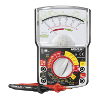
Measuring socket selection and assignment of the black and red measuring cable
DMM black red
µA,mA A
VC130-1 COM (5) mA (7) A (6)
VC150-1 COM (5) mA (7) A (6)
VC170-1 COM (5) mA (7) A (6)
- Plug the red measuring lead into the 10 A measuring socket (at currents> 200 /> 400 mA depending on the model)
or into the mAµA measuring socket (at currents> 200 /> 400 mA depending on the model). Plug the black measur-
ing lead into the COM socket.
- Select the measuring range Try to start measuring with the largest measuring range if possible, because the ne
fuse will trigger in case of excess current.
- Now connect the two test prods in series with the object to be measured (battery, circuit etc.); the display indicates
the polarity of the measured value together with the currently measured value.
As soon as a minus “-” appears for the direct voltage measuring in front of the measuring value, the meas-
ured voltage is negative (or the measuring tips have been mixed up).
- After measuring, remove the measuring leads from the measuring object and turn the DMM off. Turn the rotary
switch to the position “OFF” or turn the device off via the “POWER” switch.