Group 21 Engine
-trnjE+:
$tl
-i;6't;
Cylinder head, removal
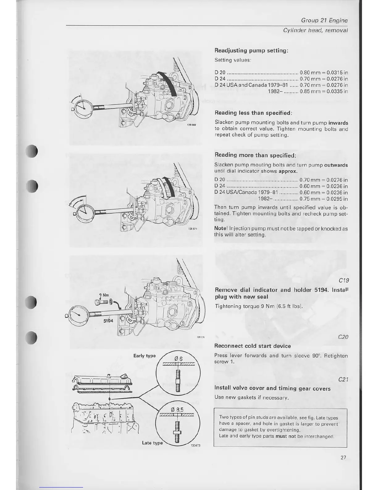
Readlusting
pump
setting:
Setting valuesi
D 20 ......-.............-....-....................... 0.80 mm
=
0.0315 in
D 24 .....-....-....-........-....-...-...-....-...... 0.70 mm
=
0-0276
in
D24USAandCanada1979
81 ......0.70mm:0.0276in
1982- .......... 0.85 mm
=
0.0335 in
Reading
less than specified:
Slacken
purnp
mounting
bolts and lurn
pump
inwards
to
obtain corecr value.
Tighten mounring
bolts and
repeat
check
of
pump
setting.
Beading
more
than
specified:
Slacken
pump
mouling bolts
and turn
pump
outwards
until dial indicator
shows approx.
D
20.....................
.....................0.70 mm
=
0.0276 in
D 24 ..........................................-...-..
0.60 mm
:
0.0236 in
D 24USA,/Canada
l97F81
............. 0.60 mm
=0.0236in
1S82 .................0.75mm=0.0295in
Th€n turn
pump
inwards until
specified va ue is ob-
tained. Tighten
mounting bolts
and recheck
punrp
set-
ting.
Notel
Injection
pump
must rot be tapped or knocked
as
this wil
alter setting.
c19
Remove dial indicator and holder 5194. lnstall
plug
with new
seal
Tishtening
torque 9 Nm
(6.5
ft
lbs).
Reconnect cold
start device
Press
ever forwards and turn
c20
sleeve 90". Retighten
c21
Install valve
cover
and timing
gear
covers
Use
new
gaskets
if necessary.
Two types
ol
pin
studs are
avaitabte, see tig.
Lare ryDes
h€ve
a spacer, and hoie in
gaskel
is larger
to
prevenl
damage
to
gasker
by overrightening,
Late ard eu ry
type
pa.ts
musr
not be inlerchanged.
/
Qa,s
'
zTazzzz
II
E
21