Group 21 Engine
Cylinder
head. installing
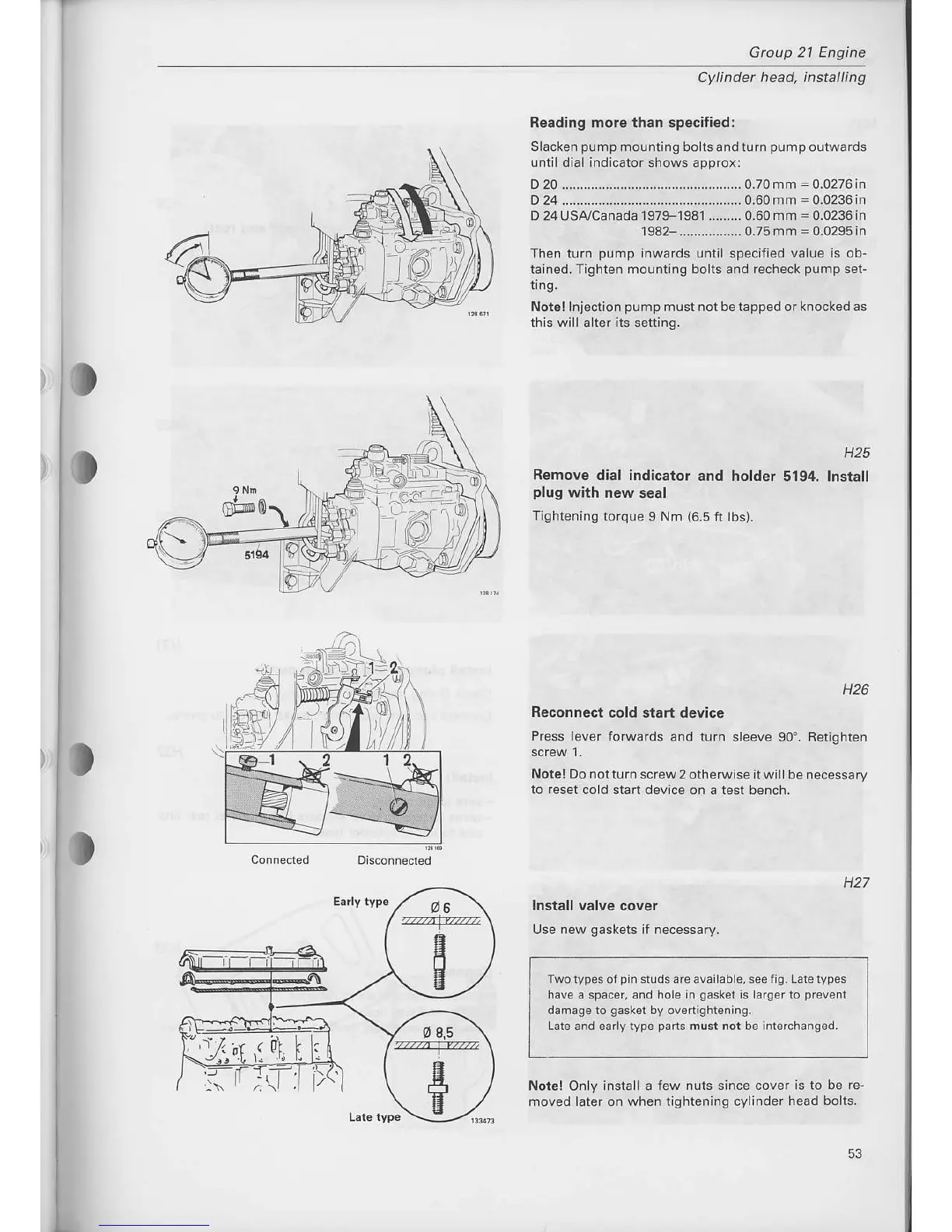
Reading more than specified:
Slacken
pump
mounting bolts and turn
pump
oulwards
until dial indicator shows approx:
D20.................................................0.70mm=0.0276in
D 24 ...--...--...--...--...-...--...-................ 0.60 mm
=
0.0236 in
D 24 USA/canada
197F1981 ......-.. 0.60 mm
=
0.0236 in
1982 .................0.75mm=0.0295in
Then
turn
pump
inwards until specified value is ob
rained. Tighten mounting bolts and recheck
pomp
set-
trng.
Note! lnjection
pump
must not be tapped or knocked as
this will
alter
its
setting.
Remove dial indicator
and
plug
with new seal
T'shtening
torque I Nm
(6.5
ft
H25
holder
5194. lnstall
o
H26
Reconnect
cold start device
Press lever forwards
and turn sleeve 90'. Retighten
Notel Do
notturn screw 2 otherwise itwill be
necessary
lo reset
cold start device on a test bench.
H27
Install valve
cover
Use
new
gaskets
if necessary.
Two
typ6s oj
pin
srudsareavailable,
seetig. Laretypes
have a spacer, and hole
in
gasket
is larger
to
pfevont
damage lo
gasket
by ovenightening,
Lale and early
rype
parts
must not be interchanqed,
Note! Only install a lew
nuts since cover is to be re-
moved laier on when lightening cylinder
head bolts.
?.i
A.EErj
li6t',t
zz7:@
ta
E
E
53