4.4 Installing the Simulator PC
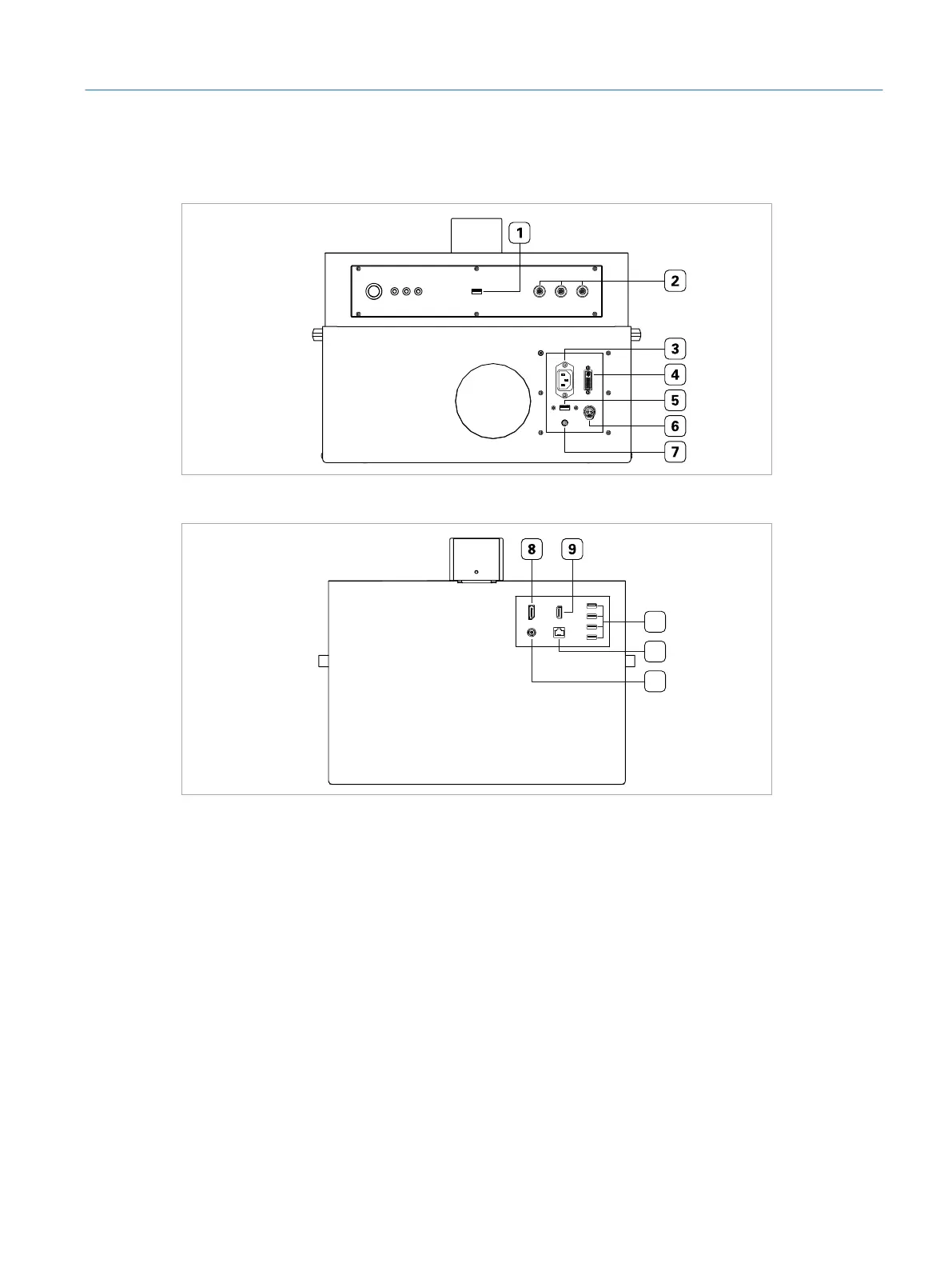
Fig. 5: Front view of the simulator PC
10
11
12
Fig. 6: Back view of the simulator PC
1 USB port for surgical interface head
2 Instrument ports
3 Power inlet for power supply cable coming from lifting column
4 DVI port for touch screen
5 USB port for touch screen USB cable
6 Touch screen power outlet
7 Audio jack for touch screen
8 DisplayPort connector for microscope
9 HDMI port for additional monitor/projector
10 USB ports for foot pedals and additional peripheral devices
11 RJ45 port
12 VRx connector for microscope
21
Installation
Eyesi Surgical Simulator – Installation and Operating Guide