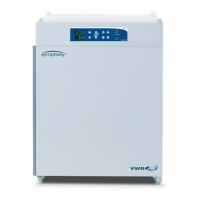
| Description of the device
24 | CO2 Incubator Basic VWR
Chapter 4
All supply connections are installed in the switchbox at the rear of the device.
Gas connection:
The gas supply line between the device and the gas supply system is connected using the supplied
connecting hoses.
CO
2
is supplied to the device through a separate connecting sleeve [1].
The process gas must be supplied to the device at a fixed pressure that has been preset within a
range of 0.8 - 1.0 bar, this must remain unchanged.
Before the gas is fed into the work space, it flows through a sterile filter with a separation rate of
99.97% for a particle size of 0.3 μm (HEPA filter quality).
Label:
The label [2] contains information about gas supply, an alarm contact terminal legend, and notes
about the electrical fusing of the device.
RS 232 interface:
Via the RS 232 interface [3], the incubator can be connected to the serial interface of a PC. This
connection allows the computer-aided acquisition and documentation of the major operating
parameters (temperature, CO
2
concentration, failure codes, etc.).
Alarm contact:
The device can be connected to an on-site, external alarm system (e.g. telephone system, building
monitoring system, visual or acoustic alarm system). For this purpose, a potential-free alarm
contact [4] is preinstalled in the device.
NOTE!
Alarm contact:
The alarm contact receives only messages caused by work space atmosphere conditions
(temperature or gas)!
Power supply connection:
The power supply connection [5] of the device is established via a cable with a connector for non
heating appliances. The holder for the two device fuses is integral to the power supply socket.