| Start-up
38 | CO2 Incubator Basic VWR
Chapter 5
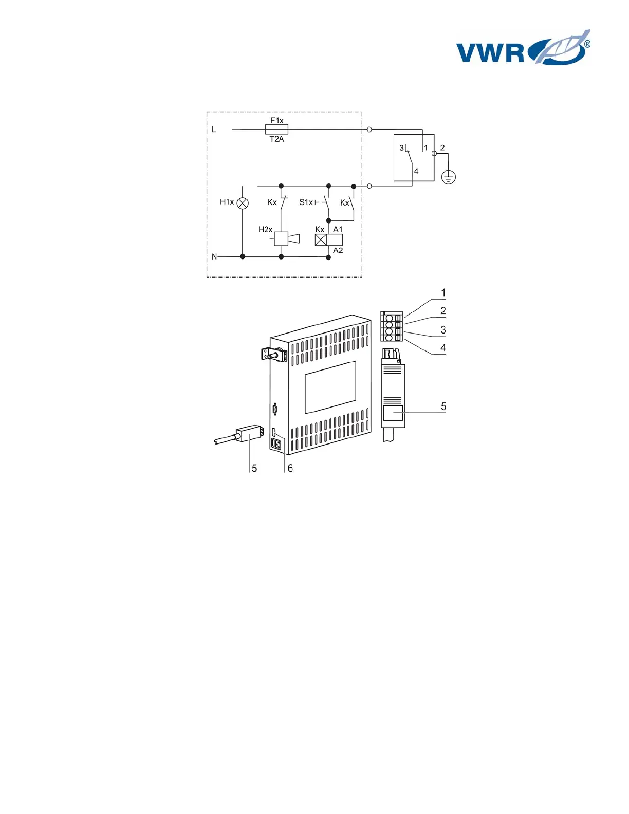
Connection example:
Figure 15 – Example of a connection scheme
The connector [5] for the connecting cable is comprised in the scope of delivery. The values for the
operating voltage of the external circuits and of the fusing of the alarm system are given in the
table above.
1. Connect the individual conductors [1] to [4] of the connecting cable as shown in the wiring
diagram.
2. Connect the connector [5] of the alarm system connecting cable to the interface [6] at the
control box at the rear panel of the device.