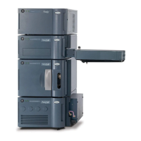
6. Partially install the valve assembly by tipping the valve assembly slightly forward and
sliding it into the column compartment.
Figure 2–15: Installing the column-selection valve assembly in column
compartment
7. Firmly connect the two, pre-wired, electrical-signal connectors, located in the compartment,
with the two corresponding connectors attached to the valve assembly.
8. Route each wiring harness to the sides of the valve, to avoid pinching the harness in the
valve-bracket assembly when the valve is fully installed.
9. Secure each bottom corner of the valve-assembly bracket into the chassis tabs.
10. Slowly press the upper valve assembly bracket inward while aligning the two captive
screws to the threaded inserts within the compartment.
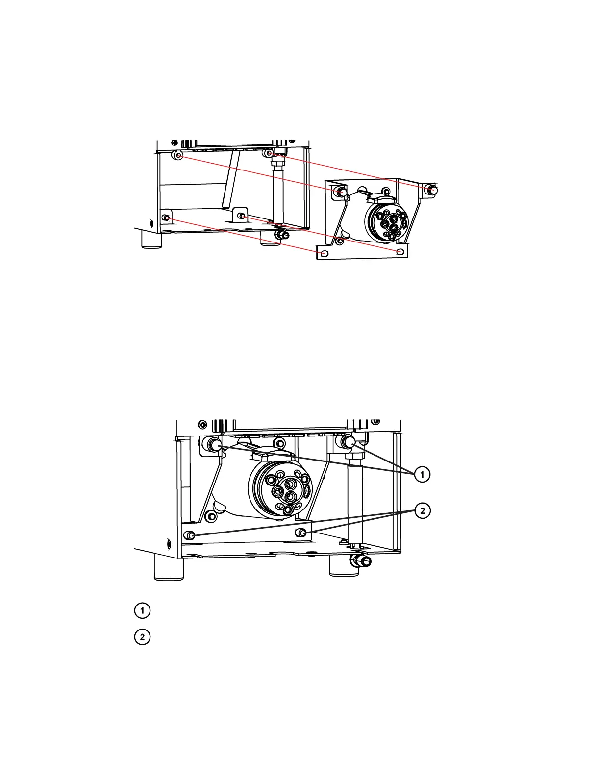
Figure 2–16: Column-selection valve installed in column compartment
Captive screws (2)
Chassis tabs (2)
11. With the captive screws aligned, finger tighten them, to retain the bracket, and then tighten
each screw using the #2 Phillips screwdriver.
12. Inspect the installation, ensuring that no portion of the wiring harness is pinched.
December 5, 2017, 715004751 Rev. C
Page 35