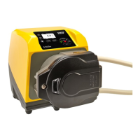
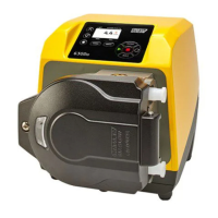
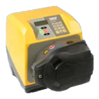
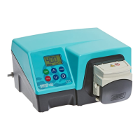
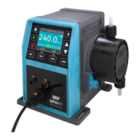
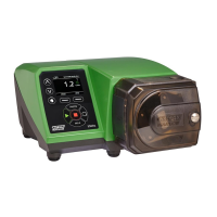
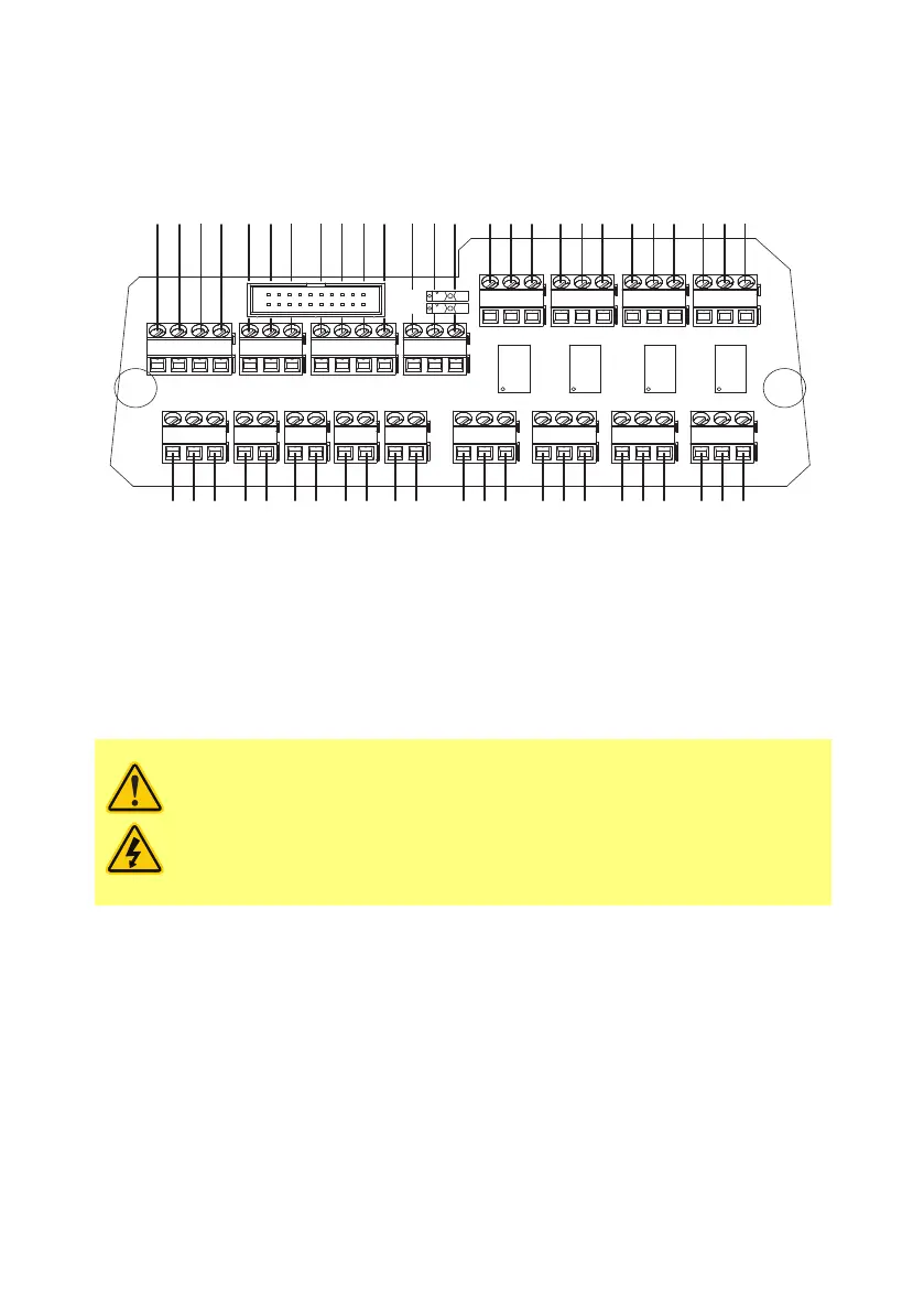
13.6 Standard N - Module
Note: Not all functions may be available, those available will depend on your pump model.
+5V
J1
J14
J15J16
J17
J10
J11
J12
J13
SW1
SW2
PL1
RL1RL2RL3RL4
J2
J3J4
J5J6J7J8J9
i/p0V
N/OCN/C
N/OCN/C
N/OCN/C
N/O
CN/C
B
I
V
Hz
0V
A
0V
+5V
+12V
-12V
(Planned)
+5Vi/p0V
+5Vi/p0V
+5Vi/p0V
i/p
0V
+10V0V
i/p
0V
i/p
0V
+12V
Commoning
Tube monitor Analog 2 Rem pot
Direction
enable link
Analog 1
Run/stop
Dose
Direction
Auto/man
(maximum +24VDC)
Spare supplies
(planned)
Tacho o/p
Freq
RS485 Relay 4 Relay 3
Relay 2 Relay 1
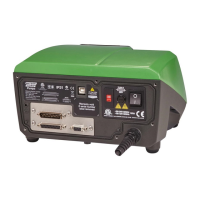
Note: It is recommended to separate the module from the pump and leave the connector PCB attached
to the pump rear. Disconnect the Module ribbon from the pump by use of the ribbon eject levers on the
connector board.
Recommended control cable: metric = 0.14sqmm - 2.5sqmm solid and 0.14sqmm - 1.5sqmm
stranded. USA = 26AWG - 14AWG solid and 26AWG - 16AWG stranded. Cable: circular. Max/min outside
diameter to ensure a seal when passed through the standard gland: 9.5mm-5mm. The cable section
must be circular to ensure a seal.
Never apply mains power to the terminals within the N module. Apply the
correct signals to the terminals. Limit signals to the maximum values shown.
Do not apply voltage across other terminals. Permanent damage, not covered
by warranty, may result. The maximum rating on the relay contacts of this
pump is 30VDC; maximum load 30W.
Note: Also suitable for low power: ie, 1mA at 5VDC minimum.
m-630un-en-08 33