12 BlueCool S-Series
5.7.5 Installing sea water lines
WARNING
Boat can sink; danger of drowning
Sea water enters when installed incorrectly
Install double hose clamps on sea water lines. Install
the two hose clamps mirror-inverted.
Notes
■
Pay attention to the minimum required diameter
of the sea water lines.
■
Only use reducers when this serves the specific dis-
tribution of the volume flows when several sys-
tems are connected to one pump.
■
The sea water lines must be installed as follows:
–
as short as possible
–
kink-free
–
Without water pockets
–
protected against rubbing.
■
Avoid 90° fittings wherever possible as they create
a considerable pressure loss, thus unnecessarily re-
ducing the sea water flow. It is preferable to install
the line in a kink-free bend.
■
On the intake side of the pump, it is advisable to
use a line with over-dimensioned cross-section, as
soiling can occur here most frequently, resulting in
an unintentional reduction of the flow rate.
Install intake line(s) so that there is a slight upward incline from
the sea water inlet to the self-contained air-conditioning unit.
Install pressure line(s) to the self-contained air-conditioning unit
and to the sea water outlet.
5.8 Installing the air ducts
CAUTION
Condensation can form on the outer surfaces of
cold air ducts.
Danger of water damage.
Completely insulate the air ducts, as otherwise con-
densed water will result on the outside of the air
duct and drip water will form.
CAUTION
Damage to objects behind installation surfaces
during sawing, drilling and screwing work.
Risk of damage to furniture, equipment, lines,
etc.
Bear in mind there may be objects behind the point
where openings for air inlet grille and supply air grille
are to be made.
5.8.1 Mounting
Notes
■
Prevent a restriction of the air supply due to exces-
sively tight bending radii of the air ducts or due to
accidental deformations.
■
Keep the air ducts as short as possible (<2.5m).
Excessively long air ducts result in a reduction in
the air quantities, and therefore in a decrease in
the cooling/heating capacity of the system.
■
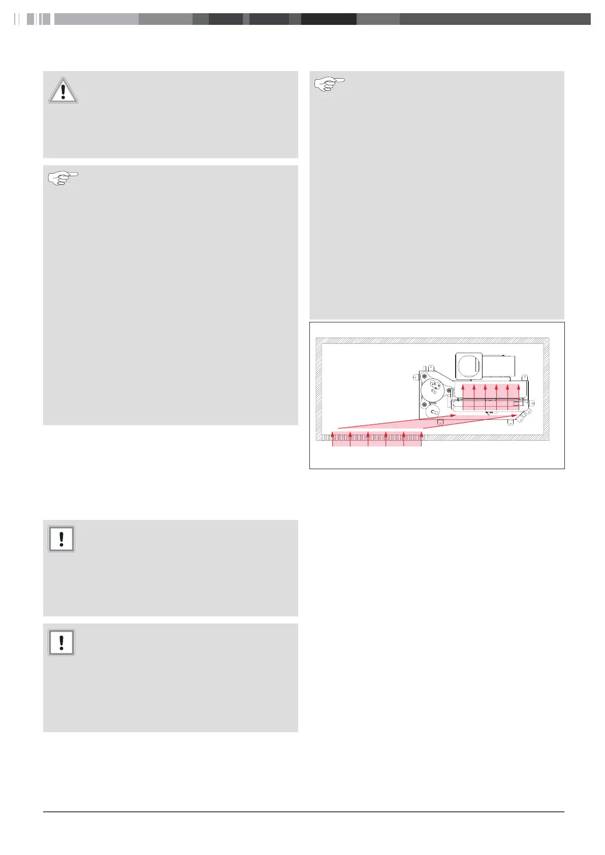
The air inlet grille should be mounted offset so
that the air flowing in does not flow directly into
the evaporator inlet. This enables the intake noises
from the fan to be considerably reduced. See
Fig.8.
■
Avoid a cold air short-circuit between the air outlet
and air inlet. These must be mounted with a suffi-
cient distance from each other.
■
Air outlets must be installed above below the ceil-
ing to ensure sufficient mixing and cooling or
heating of the cabin air.
Fig.8
Mount air inlet grille offset.
Minimum cross section of air inlet and supply air grilles
The minimum cross-sections of the air inlet and outlet air grille
and the air ducts must be taken into account for a satisfactory
functionality of the air conditioning system
 Loading...