14 BlueCool S-Series
6 Electrical Connections
6.1 General
CAUTION
Connection of electrical system carries 115
V/230 V
Danger of injuries or fatal accidents and dama-
ge to the air conditioning system or other elec-
trical devices.
Work on electrical systems which carry 115V /
230V may only be carried out by persons certified
accordingly for this purpose.
Before working on the electrical system the system
must be disconnected from the power supply.
The entire air conditioning system must be protected by an exter-
nal circuit breaker.
With the BlueCool S-Series S20 and S27, not only the power sup-
ply of the PCB, but also a separate power supply for the compres-
sor must be provided, which must also be protected externally.
6.1.1 Minimum wire cross sections
Minimum wire cross sections must be taken into account.
Information on determining the minimum wire cross-sections for
each device in the BlueCool S-Series can be found in Chapter
“13.2 Dimensions and minimum distances Type S6 - S20” on page
32 and “13.3 Dimensions and minimum distances Type S27” on
page 33.
Note
■
Earth conductors are not specified.
■
Pay attention to the following requirements:
–
Line length
–
Power consumption (same table)
–
Maximum temperatures in the vicinity of the ca-
bles
6.1.2 Installing line fuse protection
Line fuse protection must be selected corresponding to the data in
Section “14.3 Wiring diagrams” on page 37. The fuses must
also be selected in accordance with the national and local stand-
ards. Fuses of class gG for IEC and UL-type T with a tripping time
of less than 0.5 s are generally required; if a magnetic circuit
breaker (MCB) is used it must be of type B as specified in the data
in chapter “13 Technical Data” on page 30. Make sure that the
voltage, frequency and number of phases match the data of the
type used.
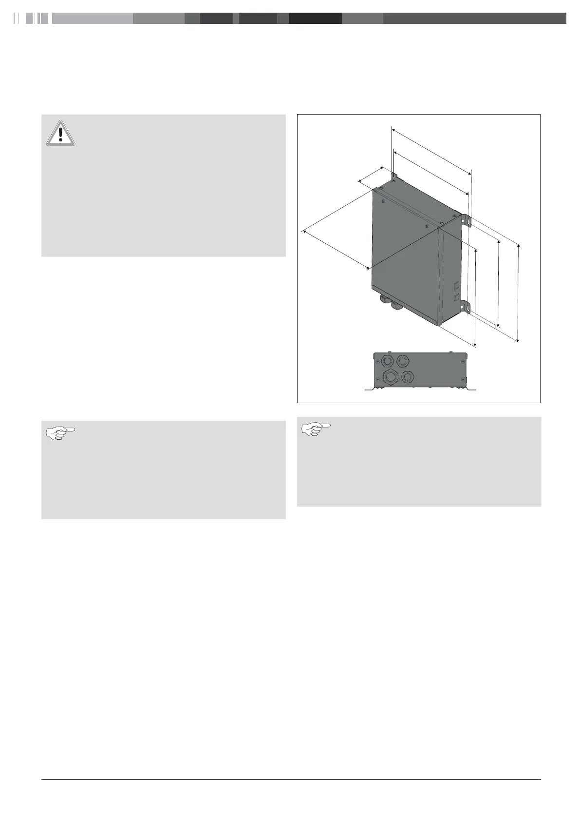
6.2 Installing the electrical box
Fig.10
277
242
214
239
83
254
310
Electrical box dimensions
Note
■
For Protection Class IP21 and higher, the connec-
tions for the control element and cabin tempera-
ture sensor and the USB connection must be direc-
ted downward.
■
Make sure that the maximum permissible ambient
temperature of 40 °C is not exceeded.
Any desired installation position may be chosen for the electrical
box if no requirements are placed on the IP protection class. For
protection class IP21 and higher, the electrical box must be in-
stalled either horizontally reclined with the cover facing upward
or vertically upright with the connections facing downward.
Install the electrical box. Make sure that the fastening screws
are accessible for opening and removal.
 Loading...