BlueCool S-Series 15
6.3 Connecting BlueCool S-Series
Note
Always refer to the wiring diagrams.
See Chapter “14.3 Wiring diagrams” on page 37.
Many electrical connections are already pre-assembled on the
BlueCool S-Series self-contained air-conditioning unit.
Connect the sea water pump. Pass connection cable through a
PG cable gland and connect to the cable terminal (Fig.21, sea
water pump). When operating several BlueCool S-Series units
with one sea water pump, observe Fig.25.
Produce the mains connection.
Guide the mains cable through the PG cable gland.
Slide the ferrite over the mains cable in the electrical box and
secure it with cable ties. Connect the phase and neutral (PEN)
conductor of the power supply cable to the cable terminal (see
Fig.21, power supply) on the pc-board.
Secure the earthing cable for the sea water pump and power
supply at the marked earthing terminal in the electrical box next
to the pc-board.
Additionally for S20 and S27:
Guide the mains cable for the compressor through the PG cable
gland and connect the phase and neutral conductor to the ex-
ternal relay.
The mains connection for the compressor must be produced via
a separate supply line (fusing 16 A with S20, 20 A with S27).
6.4 Installing soft start
It is possible to retrofit the Webasto BlueCool Soft Start in the
electrical box. Refer to the wiring diagrams in section “14.3 Wir-
ing diagrams” on page 37. Make sure that the phase and zero
conductors are installed correctly.
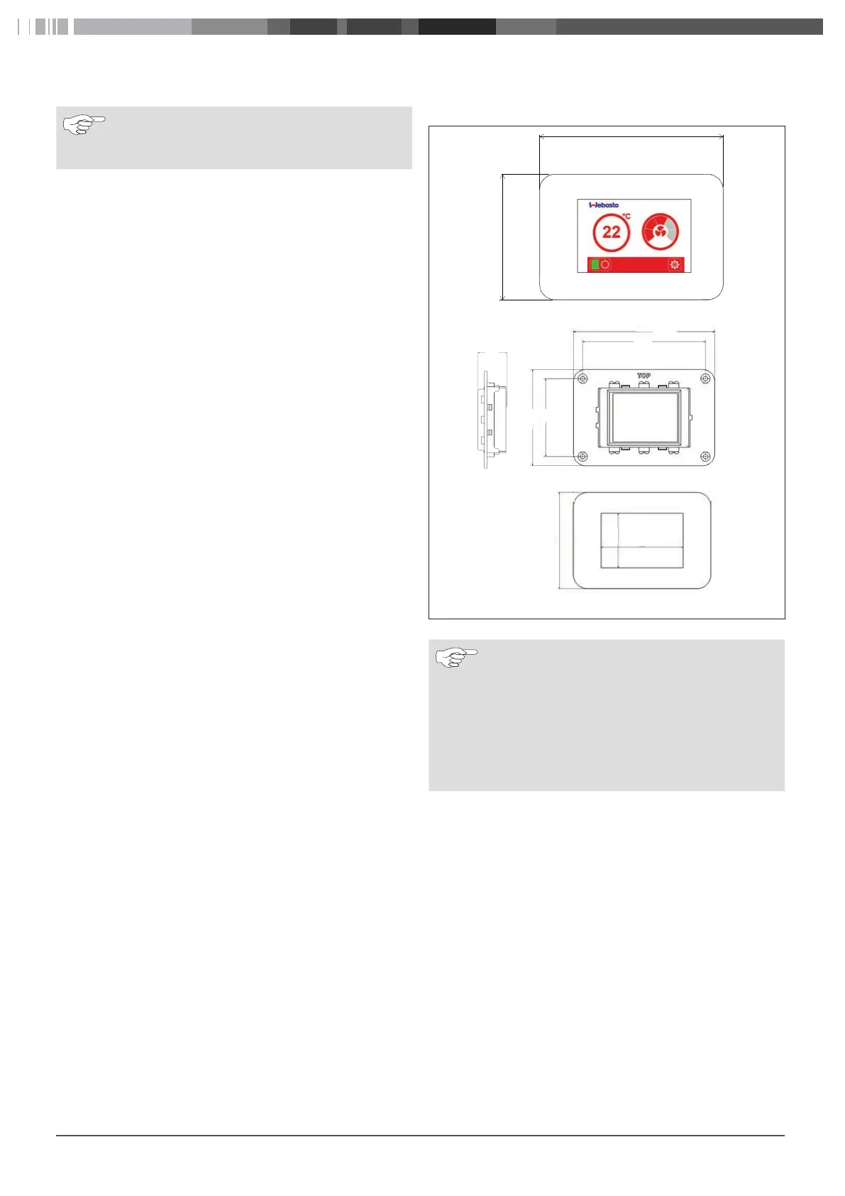
6.5 Installing the BlueCool MyTouch cont-
rol element
Fig.11
79mm
113
68
45
79
107
93
59
73
28
InstallationBlueCool MyTouch
Note
Use the supplied connection cable to connect the
control element. A commercially available 8-pin cable
with RJ45 connector (e.g. same as the power cable)
can also be used. The connection cables formerly
used by Webasto for the control element with a
membrane keypad are no longer suitable as their po-
larity has been changed.
Make the cutout for the control element in the required posi-
tion. For cutout dimensions see Fig.11.
Plug in the connector of the connection cable for the control el-
ement at the back of the control panel.
Connect the connection cable for the control element to the
electrical box from the outside.
Attach the control element with screws.
Fit trim cover.
 Loading...