38 BlueCool S-Series
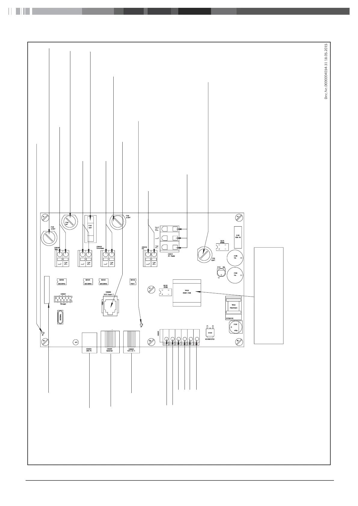
14.3.3 Layout diagram - pc-board BlueCool S-Series
Fig.21
Port CAN BUS Module
Control Panel
Cabin Temp. Sensor
0-10V EC Fan
0-10V EC Fan
High pressure switch
High pressure switch
Low pressure switch
Low pressure switch
Attention!
Please look at the label, make sure this
is the right ECU with part number
WBCL050930B or higher
LED Alive / Failure code
4/2 Way reverse (cycle) Valve
Sea Water Pump
Compressor
Evaporator temp. Sensor
LED 12V Power supply indication
Fan
AC Supply
F105 4/2 way valve 3,15AT
F104 Sea Water Pump 5AT
F103 Compressor 10AT
F102 Fan 3,15AT
F101 ECU 0,5AT
Layout diagram - pc-board BlueCool S-Series
 Loading...